Cellular Radio (GSM)
The Global System for Mobile Communication (GSM) has now been adopted worldwide as a common standard for mobile communications, although it began in the early eighties as a European mobile telephone standard to replace the various (largely incompatible) analogue mobile systems developed by different countries. The acronym (GSM) stood originally for Groupe Spécial Mobile, the working group originally formed in 1982 to develop the new system. Their objectives for the system included low cost, the efficient use of bandwidth, good speech quality, compatibility with ISDN and support for international roaming. The GSM specifications describe the functionality of each component in the system and the interfaces between them. The choice of a digital rather than an analogue system was designed to take advantage of the ability to transmit both voice and data using a single technology. The development of efficient speech compression algorithms has meant that the amount of bandwidth needed per channel has fallen, error-correcting codes can be used to improve the quality of transmission, and digital signals can be encrypted for security.
GSM uses a cellular system in which a geographical area is divided into cells, each using a different set of frequencies. A cell corresponds to the area covered by a single transmitter (or a small collection of transmitters), and the size of each cell is determined by the transmitted power. Cellular systems are based on the concept of low-power transmitters and relatively small cells, so that the same frequencies can be re-used in non-adjacent cells. The distance between cells using the same frequencies must be sufficient to prevent interference. This re-use of frequencies greatly increases the overall capacity of the system in terms of the possible number of users. A number of channels in each cell are reserved for signaling information.
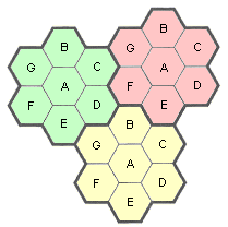
Frequency reuse in cellular systems
The cells are usually roughly circular, but are easier to model as hexagons. In the above diagram, cells are grouped in units of seven cells (A-G), and each letter indicates a different group of frequencies. There is an approximate two-cell buffer between cells using the same set of frequencies, giving good separation and minimising interference. In areas that are densely populated with users (a busy city centre, for example), the transmitted power is reduced and the cells are smaller. At the centre of each cell is a base station consisting of a computer-controlled transceiver connected to an antenna, which communicates with all of the mobile devices in the cell. In a small system, all of the base stations are connected to a single mobile telephone switching office (MTSO) or mobile switching centre (MSC). In larger systems, several MTSOs may be required, all of which will be connected to a second level MTSO, and so on. MTSOs are connected to at least one exchange in the Public Switched Telephone System (PSTN). MTSOs communicate with each other via the PSTN using a packet switching network.
At any given time, each mobile device is under the control of the base station for whatever cell it happens to be in. When the device leaves the cell, the base station detects the fact that the received signal strength is fading and asks the surrounding base stations to report the power levels they are receiving from the device. Control is transferred to the cell whose base station is receiving the strongest signal, and a message is sent to the device informing it that it is now under the control of a different base station and must switch to a new channel. This process is called handoff, and takes approximately 300 milliseconds. Channels are assigned by the MTSO. A GSM cell, identified by its cell global identity (CGI) number, is defined by the radio coverage of a base transceiver station. A location area (LA), identified by its location area identity (LAI) number, is a group of cells served by a single MSC/VLR. A group of location areas under the control of the same MSC/VLR defines the MSC/VLR area. A public land mobile network (PLMN) is the area served by one network operator.
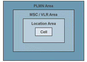
GSM network areas
The entities that form part of a GSM network include the mobile station (MS), base station subsystem (BSS), network and switching subsystem (NSS), and operation and support subsystem (OSS). The architecture of a GSM network is shown in the diagram below, which illustrates the relationship between the various entities.
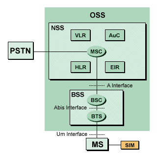
GSM network architecture
A Mobile Station consists of mobile equipment (typically a mobile phone) that includes the Subscriber Identity Module (SIM). The SIM is a smart card that gives the user access to various subscriber services. It can be removed from one mobile device and inserted into another. The SIM card is protected by a four-digit Personal Identification Number (PIN), and identifies the subscriber to the system using an International Mobile Subscriber Identity (IMSI). The mobile equipment is uniquely identified by the International Mobile Equipment Identity (IMEI). The IMEI and the IMSI are independent of one another. The Base Station Subsystem connects the Mobile Station and the Network and Switching Subsystem, and controls the radio link with the mobile station. It consists of a Base Transceiver Station (usually referred to simply as a "base station"), and the Base Station Controller (BSC). The base station houses the radio transceivers and antennae used by a network cell, and manages the radio link protocols used to communicate with the mobile device. It is usually located in the centre of a cell, and its transmitted power defines the cell's size. Each BTS may have up to sixteen transceivers, depending on the number of users in the cell. The BSC controls a group of base stations and manages their radio resources. It is principally in charge of channel setup, handover, frequency hopping, exchange functions, and transmitted power levels for each base station.
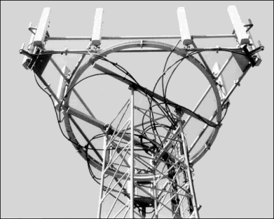
BT Cellnet base station antennae
The BTS and BCS communicate across the Abis interface (an internal BSS interface), that allows components from different suppliers to interoperate. The BSS communicates with the Mobile Station across the Um interface (also known as the air interface or radio link), and with the MSC across the A interface. The main role of the Network and Switching Subsystem is to manage communications between mobile users, to maintain database information about subscribers, and to manage subscriber mobility. The components of the network and switching subsystem are described below.
- Mobile Switching Centre (MSC) - the central component of the network and switching subsystem - performs the switching functions of the network and provides connectivity to other networks
- Gateway Mobile Switching centre (GMSC) - the interface between the mobile cellular network and the PSTN - responsible for routing calls from the fixed network to a GSM user
- Home Location Register (HLR) - a database that stores information about subscribers belonging to the area controlled by an MSC, including their current location (corresponding to the Signalling System Number 7 (SS7) address of the visitor location register associated with the terminal) and the services to which they have access
- Visitor Location Register (VLR) - when a subscriber enters the coverage area of a new MSC, the visitor location register associated with the MSC requests sufficient information about the subscriber from its corresponding home location register, so that services to the subscriber can be maintained without further reference to the HLR
- Authentication Centre (AuC) - stores a copy of the secret key stored in each subscriber's SIM card, which is used for authentication and encryption over the radio channel
- Equipment Identity Register (EIR) - a register containing information about mobile equipment, including a list of valid terminals - a terminal is identified by an IMEI - allows the identification of stolen or unauthorised terminals
- GSM InterWorking Unit (GIWU) - provides an interface to various networks for data communications
The operation and support subsystem (OSS) connects the elements of the network and switching subsystem to the base station controller in order to control and monitor the GSM system. It is also responsible for controlling the traffic load of the base station subsystem. Because of the growth in the number of base stations, some of this functionality is now carried out by the base station, decreasing the maintenance costs of the system.
GSM functions
Five main GSM functions can be defined. The transmission function is concerned with the transmission of both user information and signaling information, and involves the mobile station, base transceiver station and base station controller. The role of the radio resources management function includes establishing, maintaining and releasing communication links between mobile stations and the MSC. It is also responsible for maintaining the connection if the user moves from one cell to another ("handover"). Other procedures for which the radio resources management function is responsible include channel assignment and release, controlling transmitted power levels, and frequency hopping. Handover can occur between cells controlled by the same BSC, or between cells controlled by different BSCs (and sometimes different MSCs). Handovers are normally handled an MSC, although if (as occasionally happens) the handover involves only a single BSC, the BSC manages the handover and the MSC is simply notified. The mobile station continuously monitors its own signal strength and that of neighbouring cells (the BSC notifies the mobile station which cells it should monitor). Handover occurs either when the mobile station cannot further increase power sufficiently to continue communicating with the base station it is currently talking to, or immediately an alternative base station can offer a better quality signal.
The mobility management function is concerned with issues related to user mobility. In order to keep track of the current location of a powered-on mobile station, several location management procedures may be invoked. When a mobile station is first powered on, it performs a location update ("IMSI attach") procedure by signalling its IMSI to the network. The host MSC updates its Visitor Location Register (VLR), and sends details of the current location of the mobile station to the subscriber's Home Location Register (HLR). Further location update procedures will be performed each time the mobile station moves from one location area to another, and will also occur periodically (if an update does not occur within a specified period, the mobile station is removed from the VLR of the host MSC). When a mobile station registers in a new location, and assuming the subscriber is entitled to service in that location, the HLR sends subscriber information to the MSC/VLR to enable call routing to occur. The HLR will also send a message to the old MSC/VLR to cancel any existing registration. When a mobile station is powered off, it performs an "IMSI detach" procedure to tell the network that it is no longer connected.
Subscriber authentication is carried out using a key stored in the mobile station's SIM and the Authentication Centre (AuC).The AuC sends a randomly generated number to the mobile station, which it subsequently uses (together with the stored key and a ciphering algorithm) to generate a signed response (SRES). The mobile station generates its own version of the SRES and sends it to the AuC. If the two versions match, the subscriber will be authenticated. The mobile station's IMIE is also checked against the list of IMEIs stored in the Equipment Identity Register (EIR). If the IMEI number is white-listed, the terminal is allowed to connect to the network (Grey-listed means that the terminal is being monitored by the network due to possible problems, and black-listed means that it has been reported stolen or is not of the correct type).
The communication management function is responsible for call control, supplementary services management and short message services management. Call control includes setting up, maintaining and releasing calls (including call routing), and selecting the type of service. The number dialled by a a user in order to connect to a mobile station (the Mobile Station ISDN or MSISDN) includes a country code, a national destination code that identifies the operator, and a code that corresponds to the subscriber's HLR. If a call originates from a fixed network, it is routed via a GMSC, which requests call routing information (including a Mobile station Roaming Number or MSRN) from the HLR corresponding to the dialled MISDN number. The HLR will in turn request information from the current VLR.

Call routing for a mobile-terminating call
The operation, administration and maintenance function allows an operator to monitor and control the system, and to modify the configuration of system elements. The BSS and NSS provide all of the required information. This information is passed to the OSS, which uses it to control the network.
The GSM radio interface
Two 25 MHz frequency bands were originally allocated for the GSM system - 890-915 MHz was allocated for the uplink (from the mobile station to the base station), and 935-960 MHz band was allocated for the downlink (from the base station to the mobile station). More recently, two additional 75 MHz frequency bands have been allocated - 1710-1785 MHz for the uplink, and 1805-1880 MHz for the downlink. The GSM multiple access scheme employs a combination of frequency division multiple access (FDMA), time division multiple access (TDMA), and frequency hopping. This arrangement maximises the number of users that can be accomodated. The 25 MHz frequency band is divided into 124 x 200 KHz channels using FDMA (a 200 KHz guard band is deployed at the lower end of the band). Each channel is divided into 8 burst periods (time slots) of approximately 0.577 ms using TDMA, giving a total frame length of 4.615 ms. Channels are divided into two main categories. Common channels are used by the mobile station to request channel resources, and by the BSS for paging, to broadcast bulletin board information, and to respond to channel requests. Dedicated point-to-point channels are dedicated signalling channels or traffic channels. The dedicated signal channels are used to set up a connection, and the traffic channels are used for speech and data once the connection is established. A full-rate traffic channel (TCH/F) is a group of 26 TDMA frames called a 26-multiframe, of which 24 frames are used for traffic, one is used for control information, and one is currently unused. The multiframe has a total duration of 120 ms.
A "normal" burst is used to carry speech, data and some signalling information, and has a total length of 156.25 bits consisting of two 57-bit information fields, a 26-bit training sequence (used to keep the mobile station and base station in phase with each other), 1 stealing bit for each information block (used to indicate whether or not the current slot carries control information), 3 tail bits at each end (during the first block of tail bits the transmitted power is "ramped up", and during the second it is "ramped down"), and an 8.25 bit guard sequence (this prevents one time slot from overlapping another, and allows for some adjustment in timing to be made if required). GSM implements slow frequency hopping whereby the mobile station and base station transmit each TDMA frame on a different carrier frequency, alleviating the problems of multi-path fading. The gross bit rate achieved is 270.833 kbps. The structure of the 26-multiframe, TDMA frame and normal burst are shown below.
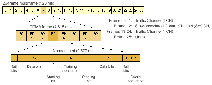
Structure of the 26-frame multiframe, TDMA frame, and normal burst
