The Synchronous Optical Network (SONET)
Up until the mid 1980s, there was a general lack of standardisation in the optical interface equipment used in high-speed digital networks. The lack of standards was seen as a significant barrier to meeting the future bandwidth needs of the telecommunications industry because of the inherent incompatibilities between network equipment from different vendors, each of whom had their own proprietary standards. In 1985 Bellcore put forward proposals for a standard optical interface that would eliminate these incompatibilities (Bellcore, now Telcordia Technologies, was a telecommunications research and development company based in the US that came into being as a result of the break-up of AT&T). Like the Plesiochronous Digital Hierarchy (PDH) that it would subsequently supersede, the Synchronous Optical NETwork (SONET) was based on a multiplexing hierarchy in which each level multiplexed together a number of data streams from the level below it. Unlike PDH, the entire SONET network was intended to transmit data at a bit rate that was synchronised across the entire network. SONET networks today frequently combine time division multiplexing (TDM) with dense wavelength division multiplexing (DWDM) to maximise the bandwidth of a single optical fibre. The resulting specification was described in the ANSI standard T1.105 published in 1988.
The SONET specification defines both optical carrier (OC) interfaces and their electrical counterparts. SONET was designed to provide a scalable, generic synchronous transport mechanism in which the frame overhead is largely independent of the payload. As such, it is able to accommodate a range of different traffic types, including Asynchronous Transfer Mode (ATM), TCP/IP and Ethernet. It can also accommodate existing PDH data streams. The signal overhead includes comprehensive network management and performance information, enabling the network to be configured, managed and monitored from a central location using standard network elements and a telecommunications management network.
The network architectures available for SONET allow significant redundancy to be built in to the system, engendering fault tolerance. In addition, mechanisms exist for the automatic handling of many types of network error. Perhaps one of the most important differences between PDH and SONET is the ability to add or drop tributaries to or from a high capacity carrier without having to completely de-multiplex the carrier first. This eliminates much of the delay associated with such activities in PDH networks, and significantly reduces both operational complexity and the cost of network equipment.
The SONET signalling hierarchy
The lowest level carrier in SONET is the Synchronous Transport Signal 1 (STS-1) which has a bit rate of 51.84 Mbps. In its optical form, the signal is referred to as Optical Carrier 1 (OC-1), although the terms STS-1 and OC-1 are often used synonymously. In order to remain compatible with existing low-level carrier and channel transmission rates, the frame rate of 8,000 frames per second (or one frame every 125μs) was retained for SONET. An STS-1 frame thus consists of 810 bytes in total (810 bytes x 8 bits per byte x 8000 frames per second = 51,840,000 bits per second). The frame includes 27 bytes of header information (referred to as overhead), leaving 783 bytes for the payload. Instead of transmitting the overhead at the beginning of the frame however, it is interleaved with the payload data. Each 90-byte sequence (of which there are nine per frame) consists of 3 bytes of transport overhead (TOH) followed by 87 bytes of payload data. The diagram below represents the frame structure as a block consisting of 9 rows of 90 columns for the sake of convenience.
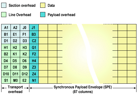
The SONET STS-1 frame structure
The payload is referred to as the Synchronous Payload Envelope (SPE), and the first column of the SPE contains 9 bytes of path overhead (POH). The SPE also includes 18 stuffing bytes, leaving a net payload capacity of 756 bytes (this is sufficient to accommodate a full PDH DS3 frame).The next level of the SONET multiplexing hierarchy is STS-3 (OC-3) which combines three STS-1 signals to give a bit rate of 155.52 Mbps. The STS-3 frame is created by interleaving the bytes from each of the three STS-1 frames together to give a total frame size of 2,430 bytes. Like all SONET frames, a single STS-3 frame is transmitted in 125μs. Four STS-3 signals can in turn be multiplexed together to create an STS-12 (OC-12) signal with a bit rate of 622.08 Mbps. The multiplexing rates currently available for SONET are shown in the table below. Note that, because of the asynchronous nature of the data streams forming the payload of an STS-1 frame, the payload itself is allowed to "float" with respect to its starting position within the STS-1 frame structure. The STS-1 transport overhead therefore includes a pointer (specified by the H1 and H2 bytes within the transport overhead) that indicates exactly where the STS-1 SPE for a particular frame begins (this is the location of byte J1 at the top of the path overhead column). The implications of this are discussed in more detail shortly.
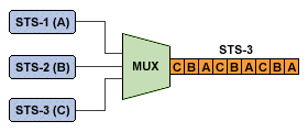
Byte-interleaved multiplexing in SONET (3 x STS-1 : 1 x STS-3)
| Level | Line Rate (Mbps) | Data rate (Mbps) |
|---|---|---|
| STS-1 (OC-1) | 51.84 | 50.112 |
| STS-3 (OC-3) | 155.52 | 150.336 |
| STS-12 (OC-12) | 622.08 | 601.344 |
| STS-24 (OC-24) | 1,244.16 | 1,202.688 |
| STS-48 (OC-48) | 2,488.32 | 2,405.376 |
| STS-192 (OC-192) | 9,953.28 | 9,621.504 |
| STS-768 (OC-768) | 39,813.12 | 38,486.016 |
| STS-3072 (OC-3072) | 159,252.48 | 153,944.064 |
SONET STS-1 Overhead Bytes
The tables below briefly summarise the function of the overhead bytes within the SONET STS-1 frame structure.
| Byte | Function |
|---|---|
| A1,A2 | Frame synchronisation |
| B1 | Quality monitoring, parity bytes |
| D1-D3 | Network management |
| E1 | Voice connection |
| F1 | Maintenance |
| J0 (CI) | Transmitter indication |
| Byte | Function |
|---|---|
| B2 | Quality monitoring, parity bytes |
| D4-D12 | Network management |
| E2 | Voice connection |
| H1,H2 | Pointer |
| H3 | Pointer action |
| K1,K2 | Automatic protection switching (APS) control |
| S1 | Clock quality indication |
| M1,M0 | Communication error return message |
| Z1 | Timing source information |
| Z2 | Line far end information |
| Byte | Function |
|---|---|
| J1 | Path trace byte |
| B3 | Quality monitoring |
| C2 | Container composition |
| G1 | Communication error return message |
| F2 | Maintenance |
| H4 | Multi-frame indication |
| Z3 | Maintenance |
| Z4 | Automatic protection switching |
| Z5 | Tandem connection monitoring |
SONET pointers
The synchronous payload envelope (SPE) for an STS-1 frame does not have to be contained completely within a single frame. In fact, the SPE typically crosses frame boundaries. This allows for variations in frequency between payload signals, and also allows non-synchronous traffic to be carried by the synchronous network. The last 10 bits of the H1 and H2 bytes in the STS-1 transport overhead contain a pointer value that gives the location of the start of the SPE within the frame. This is given as the offset in bytes between the H3 byte and the first byte of the SPE (this is the J1 byte in the SPE's path overhead), ignoring the transport overhead bytes. A valid pointer value can range from 0 to 782. In the example below, the pointer value stored in H1/H2 gives an offset of 190 bytes from byte H3 for the start of the SPE. It is worth noting here that some smaller networks may operate in locked mode, where the location of the frame payload is fixed at a known value. This has been used in particular for the interface with ATM networks, although a floating mode is the preferred approach in most other scenarios as it allows far more flexibility in the distribution of payloads.
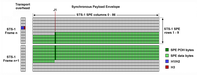
The SPE typically crosses frame boundaries
Although the transmit and receive clocks used by various SONET network elements are intended to be synchronised throughout the SONET network, in reality there are often small variations that can cause differences in timing with respect to incoming and outgoing signals. If the incoming clock is faster than the outgoing clock, the receive buffer will accumulate data faster than the rate at which it can be transmitted. Conversely, if the incoming clock is slower than the outgoing clock, there will at some point be no data in the receive buffer to transmit. The solution to the problem is to increment or decrement the pointer value stored in H1/H2 accordingly. If the pointer is decremented (i.e. to accommodate a faster incoming clock), an additional data byte is transmitted in the H3 byte within the transport overhead, increasing the size of the payload by one byte to 784 bytes. If the pointer is incremented to compensate for a slow incoming clock, a dummy byte (or stuff byte) is transmitted in the byte immediately following H3 in the SPE, reducing the payload size to 782 bytes.
Decrementing the SPE pointer is termed negative justification, while incrementing it is called positive justification. Bear in mind that under normal circumstances the pointer value will not change from one frame to the next (i.e. the start of the SPE will not change). In order to signal to the receiver that the pointer value must be adjusted, the pointer bits within bytes H1 and H2 (the 10 least significant bits) can be used to signal a change. The diagram below illustrates the way in which the H1 and H2 bytes are normally configured. The four most significant (leftmost) bits are the New Data Flag (NDF). The next two bits are not used, while the last ten (least significant) bits provide the pointer value as an offset (in bytes) between the H3 byte and the location of the start of the SPE (the J1 byte in the path overhead). In the example below, the pointer value gives an offset of 217 bytes (00110110012 = 21710).
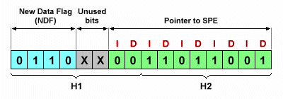
The H1 and H2 bytes provide a pointer to the start of the SPE
You will note that in the above diagram, the pointer bits are alternatively labelled "I" and "D", which stand for increment and decrement respectively. In order to signal an increment in the pointer value, the increment bits are inverted. To signal a decrement in the pointer value, the decrement bits are inverted. At the receiving end, the payload is recovered from the appropriate location after examination of the pointer bits to see whether the pointer value has been adjusted from that seen in the previous frame. In the example illustrated below, a sequence of frames is transmitted in which the pointer value is to be decremented. The first frame is transmitted as usual with a pointer value that points to the start of the SPE. In the second frame the SPE is to undergo negative justification, so the decrement ("D") bits are inverted, and the H3 byte contains data for one frame. The receiver detects that the "D" bits have been inverted, recovers the data byte from H3, and decrements the value of the stored pointer value to indicate the new starting point for the payload (which has been moved to the left by one byte).
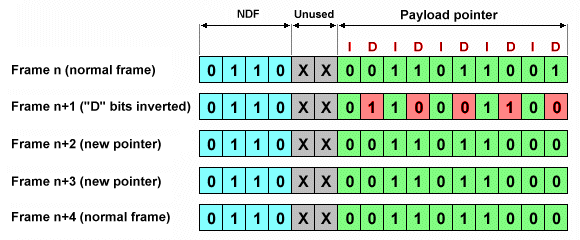
Sequence of events when decrementing a pointer (LOH bytes H2/H3)
The pointer value now gives an offset of 216 bytes (00110110002 = 21610). Note that the "I" and "D" bits within the pointer value cannot be used again to increment or decrement a pointer until the new pointer value has been received for three consecutive frames. Note also that only line terminating equipment (LTE) may perform negative or positive justification, since it involves manipulation of the line overhead bytes H1, H2 and H3. The illustration below shows the effect of negative justification on payload placement.
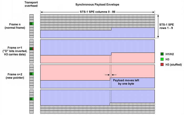
Negative justification (payload pointer is decremented from 217 to 216)
To signal an increment in the pointer value, the increment ("I") bits are inverted. As with negative justification, the payload is recovered at the receiving end from the appropriate location after examination of the pointer bits to determine whether the current payload pointer is still valid. In the example below, a sequence of frames is transmitted in which the pointer value is to be incremented. The first frame is transmitted as usual with a pointer value that points to the start of the SPE. In the second frame the SPE is to undergo positive justification, so the increment ("I") bits are inverted, and the byte immediately following the H3 byte is stuffed (i.e. it is a dummy byte) for one frame. The receiver detects that the "I" bits have been inverted, and increments the value of the stored pointer value to indicate the new starting point for the payload (which has this time been moved to the right by one byte).
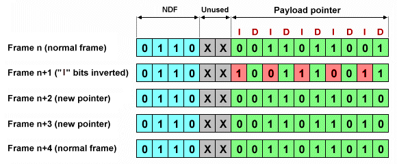
Sequence of events when incrementing a pointer (LOH bytes H2/H3)
The pointer value now gives an offset of 218 bytes (00110110102 = 21810). The illustration below shows the effect of negative justification on payload placement.
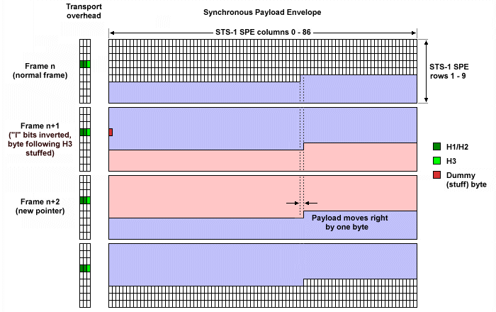
Positive justification (payload pointer is incremented from 217 to 218)
In cases where the pointer value is to be changed by values greater than 1, the New Data Flag (NDF) can be used instead of the "I" and "D" bits. In the frame where the new pointer value is to be introduced, the bits in the NDF are inverted to give a value of 1001. This signals the receiver that a new pointer value has been set, which is effective immediately. As for the "I" and "D" bits when performing positive and negative justification, the NDF bits can only be used to set a new pointer every fourth frame. Furthermore, if the special cases where a positive pointer value adjustment is made from 782 to 0 or vice versa, the system will ignore the new pointer for exactly one frame. The new pointer will thus become a valid pointer only in the second frame following the frame in which the NDF bits were inverted.
SONET network architecture
SONET networks employ a relatively small number of network elements (NEs), each of which derives their timing information from a highly accurate and stable caesium clock located somewhere within the network. These network elements are connected together using fibre optic links in various configurations, and the abstract layered model commonly used to describe a SONET network relates almost entirely to the level at which a particular network element operates within the network topology. In some cases, a single network element can operate at a number of levels. There are four layers in the model, which are briefly described below:
- Photonic - this layer carries the optical signals and includes the optical fibres that connect the various network elements together. The main considerations here are the optical characteristics of the fibre and the interfaces between the fibre and the section terminating equipment (STE).
- Section - a section is a single physical optical fibre link between any two adjacent network elements (including optical regenerators), and transmission over a section is controlled using the section overhead (SOH) bytes embedded within the SONET frame. Section terminating equipment is responsible for adding the section overhead to create the SONET frames, for converting electrical signals to optical signals and vice versa, and for signal scrambling (see below).
- Line - a line is the physical connection between two adjacent SONET network elements (excluding optical regenerators). It differs from a section only in as far as it may include, but cannot be terminated by, one or more network elements whose purpose is simply to regenerate and amplify weak signals. Transmission over a line is controlled using the line overhead (LOH) bytes embedded within the SONET frame. The responsibility for generating the line overhead and multiplexing the STS-1 SPE signals falls to the line terminating equipment (LTE).
- Path - a path is the complete path followed by a signal from the point at which it enters the SONET network to the point at which it leaves the network. Transmission over a path is controlled using the path overhead (POH) bytes embedded within the SONET frame (these bytes occupy the first column in the Synchronous Payload Envelope (SPE). Path terminating equipment (PTE) is responsible for mapping non-SONET tributary signals into the STS-1 SPE and creating the path overhead.
Because timing information is embedded within SONET optical signals, the presence of long strings of ones or zeros in an incoming signal would make it quite difficult for a receiver to recover the embedded clock signal. To facilitate clock signal recovery at the receiver therefore, the signal (apart from certain key bytes in the section overhead) is scrambled. The signal is descrambled at the receiver in order to restore the signal to its original state.
The most basic network element in a SONET network is the terminal multiplexer, which multiplexes incoming non-SONET signals (for example, PDH DS1 or DS3 signals) onto a higher-speed SONET link. A simple SONET network could consist of two terminal multiplexers connected by a fibre link. For distances greater than can be accommodated by a single fibre run, an optical regenerator can be used to reconstruct and amplify the signals where necessary. Other elements in a basic SONET network could include an add drop multiplexer (ADM) which incorporates the necessary hardware to access the multiplexed data stream and insert individual channels into it or extract them from it, while allowing other traffic to pass through the multiplexer unchanged. Cross-connect network elements may also be deployed within the network, and are used to switch, combine or redirect data signals. All of these network elements are section terminating equipment (STE), and all except the optical regenerator are line terminating equipment (LTE). Any elements that connect a non-SONET signal to a SONET network are path terminating equipment (PTE). The diagram below illustrates the various layers.
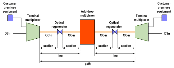
Section, line and path layers in a SONET network
Various SONET architectures may be used that are designed to make the best use of the available bandwidth while ensuring that sufficient redundancy is built into the network to maintain connectivity even in the event of a failure somewhere in the network, thus preventing loss of service. The simplest of these architectures is a point-to-point system that incorporates Linear Automatic Protection Switching (or just Linear APS). The system employs two fibre pairs, one working pair and one protection pair (this is sometimes called 1+1 architecture). Both pairs carry the same data simultaneously, with the protection pair providing the required redundancy. In order to reduce the likelihood of both fibre pairs being affected by the same problem at the same time, the pairs may be routed via different physical locations (a principle referred to as route diversity).
Switching may be either unidirectional or bidirectional. In unidirectional operation, if a problem occurs with one of the working pair fibres the corresponding fibre of the protection pair is used instead. In bidirectional operation, traffic in both directions must be carried on the same pair of fibres. In the event of a problem, all operations are switched from the working pair to the protection pair. The network elements at each end of the network link monitor the state of both the working pair and the protection pair circuits to determine if and when switching must occur. For reasons of economy, a variation on this architecture provides a single protection pair as backup for a number of working pairs (this is referred to as a 1:N architecture). In the event of two or more working pairs suffering failures at the same time, the working pair with the highest priority traffic is given preference.
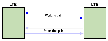
A 1+1 linear automatic protection switching system
SONET networks are often physically configured as rings, particularly within metropolitan areas. One widely used ring-based architecture is the Unidirectional Path-Switched Ring (UPSR). UPSR provides a two-fibre unidirectional path-switched ring in which traffic travels in both directions simultaneously. In the illustration below for example, traffic entering the network at node A and leaving the network at node C travels via the primary ring in a clockwise direction. A copy of the traffic is also transmitted in the anti-clockwise direction on the secondary (protection) ring.
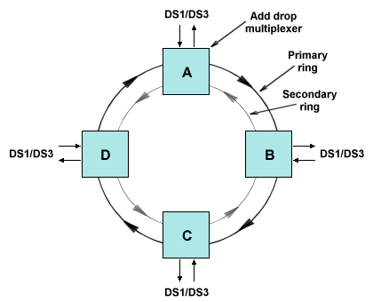
A Unidirectional Path-Switched Ring (UPSR)
Traffic entering the network at node C bound for node A also travels on the primary ring in a clockwise direction and on the protection ring in the anti-clockwise direction, completing the circuit between the two nodes (note that if the traffic between nodes A and C is utilising the full bandwidth of the primary ring, nodes B and D become simply pass-through nodes). If a broken fibre or some other failure affects the traffic on the primary ring, service will switch to the secondary ring. The exit node monitors the traffic on both rings, and can switch individual paths or tributaries between the primary and secondary ring independently of the entry node. Because no communication is required between the exit and entry nodes to enable switching to take place, the switching can take place much faster than is the case with line-switched systems. The illustration below shows the occurrence of a broken fibre between nodes B and C.
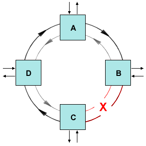
A fibre break between nodes B and C on the UPSR
When the break occurs, the receiver on the primary ring at node C detects a loss of signal (LOS) for the carrier, and inserts an alarm indication signal (AIS) into each affected path. The drop node (in this case also node C) detects the AIS and performs a path switch to the secondary ring for each affected path (because the break is adjacent to node C, this will be all of the paths terminating at node C). When the break in the fibre pair between nodes B and C is repaired, there is no requirement for node C to immediately switch each path back to the primary ring, as this would entail a further interruption (the 50 milliseconds or so required to complete the switch) in transmission. Some equipment vendors have nonetheless implemented an optional feature which causes operation to switch back to the primary ring (when this becomes possible) if enabled.
A second type of ring, the bidirectional line-switched ring (BLSR), can also be implemented as a two-fibre ring. As the name suggests, switching takes place at the line layer, unlike what happens with the UPSR. There is also no transmission of redundant copies of the traffic from the point of entry to the point of exit. Instead, in the case of a network failure, the node closest to the point of failure will re-route the traffic. Under normal circumstances traffic will be routed in both directions around the ring, so that (with reference to the diagram below) traffic entering the network at node A and exiting at node B will travel clockwise, while traffic entering the network at node B and exiting the network at node A will travel anti-clockwise. Potentially, far more use can be made of the available network bandwidth than for a UPSR, especially if an ideal scenario exists in which all traffic is between adjacent nodes.
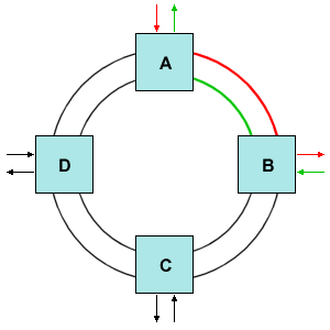
A Bidirectional Line-Switched Ring (BLSR)
In the BLSR, when a break occurs (for example, between nodes A and B), traffic is re-routed using line-switching (as opposed to path switching) as shown in the illustration below. In the hypothetical scenario described in which a break occurs between nodes A and B, traffic is re-routed the long way around the ring. Assuming that node B initiates switching, it will signal the switch to node A using the K1 and K2 bytes within the transport overhead. Obviously in this scenario, any additional traffic being carried on the ring prior to the break occurring must give way to the traffic between nodes A and B, assuming that this traffic has priority. BLSR networks are more complex (and hence more costly) than UPSR networks, but make better use of the available network bandwidth. The requirement for nodes to communicate when a break occurs increases the time required for a switch to be implemented to 50 milliseconds however, which limits the number of nodes on a BLSR to sixteen.
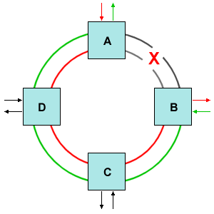
A fibre break between nodes A and B on the BLSR
A variation on the BLSR uses a four-fibre ring. One fibre pair is used to route traffic in the same manner as for the two-fibre version, with the second fibre pair acting as a protection ring. If a break occurs in the working pair, a span switch is performed so that traffic between the nodes on either side of the break is routed over the protection ring (this is essentially the same as what happens with 1:1 protection in a point-to-point system). In the event of a break affecting both rings, then a ring-switch occurs that routes traffic away from the break in the same manner as that described above for the two-fibre version. If multiple failures occur on the same ring, both span-switching and ring-switching may be used simultaneously. In a four-fibre ring, unused portions of the working ring and the protection ring may be used to carry additional traffic, increasing bandwidth utilisation. In the event of breaks in the ring however, some or all of the additional traffic being carried may have to be dropped in favour of protected traffic. One of the main drawbacks of this type of system is the cost involved in providing the additional cabling and network equipment required.
Virtual tributaries and payload mapping
At the bottom of the SONET multiplexing hierarchy, the STS-1/OC-1 carrier has a gross line bit rate of 51.84 Mbps, with a payload capacity of 50.112 Mbps. Not all of the traffic streams transported over SONET require this amount of bandwidth. Indeed, many traffic streams require only a fraction of this bandwidth. A number of relatively low bandwidth data streams have been defined to address this issue and are collectively referred to as virtual tributaries (VTs). One type of virtual tributary commonly used in North America (and Japan) is the VT1.5 which has a gross line bit rate of 1.728 Mbps, which is sufficient to accommodate a T1/DS1 signal. The European equivalent is the VT2 tributary which, at a gross line bit rate of 2.304 Mbps, is designed to transport an E1 signal. The different types of virtual tributary currently in use are summarised below (note that a DS3 or E3 signal will both maps directly into an STS-1 SPE and therefore do not require their own virtual tributary).
| VT type | Gross bit rate | Typical payload |
|---|---|---|
| VT 1.5 | 1.728 Mbps | T1/DS1 |
| VT 2 | 2.304 Mbps | E2 |
| VT 3 | 3.456 Mbps | DS1C |
| VT 6 | 6.912 Mbps | DS2 |
The process by which the various virtual tributaries are organised within an STS-1 synchronous payload envelope is called mapping. As we have already seen, an STS-1 frame consists of 90 columns and 9 rows, giving a total of 810 bytes per frame. The first three columns form the transport overhead (TOH) for the frame, leaving 87 columns for the synchronous payload envelope (SPE). Of these 87 columns, the first column is reserved for the path overhead (POH) while a further two columns (18 bytes in total) are set aside for stuff bytes. The stuff bytes occupy columns 29 and 58 within the SPE relative to the start of the SPE within the frame structure (not the frame structure itself). The virtual tributaries are organised into 7 groups known as virtual tributary groups (VTGs), each of which has a fixed size of 432 bytes regardless of the type of virtual tributary it contains.
Whilst the STS-1 frame itself may contain a number of different types of virtual tributary, a virtual tributary group may only contain virtual tributaries of the same type. A VTG may thus contain a single VT6, two VT3s, three VT2s or four VT1.5s. Within the STS-1 SPE, bytes from each VTG are interleaved as shown in the diagram below such that one byte from each VTG is inserted into the frame in turn, starting with VTG 1. If the VTG itself consists of multiple tributaries (for example, four VT1.5s), the bytes from each virtual tributary are also interleaved within each group. It should also be pointed out at this stage that seven VTGs with a fixed size of 432 bytes each will obviously not fit into a single STS-1 frame with a payload capacity of only 756 bytes (7 x 432 = 3024 bytes). To transmit the complete seven VTG sequence requires the capacity of four STS-1 frames (4 x 756 =3024 bytes). This four-frame sequence is often referred to as a VT superframe. The two least significant (rightmost) bits in the H4 byte within the STS-1 SPE path overhead are used to identify the number of the next SONET frame within a VT superframe. A binary value of 00 indicates that the next frame is the first in the multi-frame sequence, while a binary value of 11 (310) indicates that the next frame is the last in the sequence.
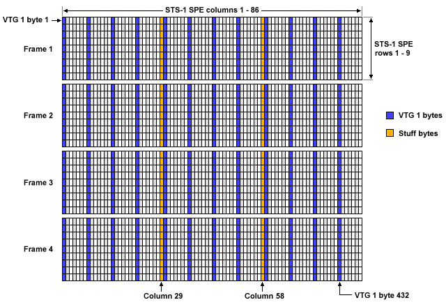
A VTG mapping within a SONET VT superframe
Just as the STS-1 transport overhead contains a pointer to the start of the STS-1 SPE within the frame, each virtual tributary group contains four bytes of VT pointer for each of its constituent virtual tributaries. A VTG containing a single VTS virtual tributary, for example, comprises 428 bytes of VT SPE and 4 bytes of VT pointer. A VTG containing four VT1.5 virtual tributaries, on the other hand, contains 104 bytes of VT SPE and 4 bytes of VT pointer for each virtual tributary. The virtual tributary SPE itself contains path overhead (POH) and payload data. The path overhead always consists of a total of four bytes regardless of the virtual tributary type, and the four POH bytes are distributed throughout the VT SPE separated by a fixed number of payload bytes. The structure of the various virtual tributary types is illustrated below.
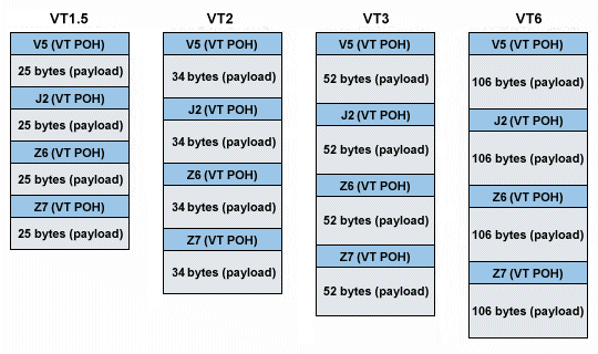
Virtual tributary SPE structure for VT1.5, VT2, VT3 and VT6 virtual tributaries
The bytes comprising the VT POH are briefly described in the table below:
| Byte | Description |
|---|---|
| V5 | Used for error performance monitoring |
| J2 | Path trace byte |
| Z6 | Tandem connection monitoring |
| Z7 | Automatic protection switching |
A VT payload pointer is present in the STS-1 superframe for each virtual tributary in the superframe. The pointer for a given virtual tributary identifies the location of the start of that virtual tributary's SPE (the V5 byte). Just as the H1, H2 and H3 bytes enable the STS-1 SPE to float within the STS-1 frame, so the VT pointer allows the VT payload to float within the VT SPE by providing the ability to increment, decrement and change pointer values. There are four pointer bytes (designated as V1, V2, V3 and V4) for each virtual tributary. Bytes V1 and V2 contain a 10-bit tributary pointer, a 2-bit size specifier (not used for SONET), and a 4-bit New Data Flag (NDF). The range of values that can be specified by the 10-bit virtual tributary pointer depends on the type of tributary it is pointing to, as follows:
VT1.5 0 - 103
VT2 0 - 139
VT3 0 - 211
VT6 0 - 427
Byte V3 fulfils a similar role for the virtual tributary that the H3 byte does for the STS-1 SPE in that it will contain data in the event of a negative justification of the payload, and will otherwise contain a value of zero. Byte V4 is reserved for future use. One VT pointer byte for each tributary is transmitted in each STS-1 frame, so transmission of all four tributary pointer bytes is spread over the complete multi-frame sequence. The VT pointer bytes are always located within the first 28 byte sequence following the J1 path overhead byte in each STS-1 frame. If the seven virtual tributary groups all carry VT1.5 virtual tributaries, all 28 byte locations will be used since there will be four virtual tributaries per VTG. Conversely, if they all carry VT6 virtual tributaries (as is the case in the example illustrated below), only seven of the byte locations will be needed. The numbers shown in the diagram indicate the VT6 pointer locations, and each number represents a group of seven bytes (one for each VT6 virtual tributary). The 10-bit pointer value carried in the V1 and V2 bytes for each virtual tributary always gives the offset in bytes (not including any pointer bytes) from the V2 byte for the start of the payload, which is the virtual tributary's first POH byte (V5). In the example shown, an offset of 117 bytes is indicated for all seven VT6 virtual tributaries.
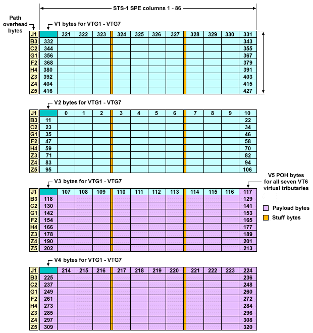
The virtual tributary payload can float within the VT SPE
Broadband services
Although low-level non-SONET tributaries can carry many types of traffic including ATM, some types of service require more bandwidth than can be accommodated by a single STS-1 payload (high volume ATM, for example). For services that require a large bandwidth, multiple STS-N synchronous payload envelopes can be effectively merged into a single much larger data pipe using contiguous concatenation. ATM traffic is typically carried in an OC-12c, for example, which is created by concatenating the payload of four STS-3c signals. Each STS-3c payload is in turn created by concatenating the payload of three STS-1 signals.
The advantage of performing this concatenation is that a 600 Mbps ATM signal can effectively be accommodated within a single synchronous payload envelope within the OC-12c. When STS-1 SPEs are concatenated, the payload pointer in the first frame points to the beginning of the frame's SPE, but all three SPEs are aligned to the pointer in the first frame in order to create a contiguous payload envelope. The payload pointers in the remaining two frames do not contain pointer information. Instead, they contain a concatenation indicator (CI) that identifies the current frame's payload as part of a larger, concatenated payload. The other path overhead bytes in the last two frames are replaced by data bytes. A similar process takes place when concatenating four STS-3c SPEs to form an OC-12C SPE (see below).
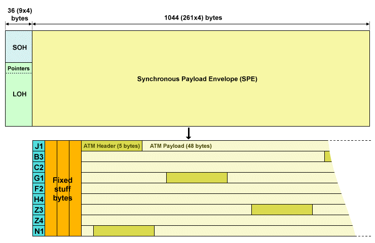
An OC-12c frame can carry ATM data at a data rate of 599.04 Mbps
Synchronising the network
All network elements in a SONET network are synchronised to one or more central reference clocks (known as stratum 1 sources) that generate clock signals in accordance with ANSI recommendation T1.101. These clock signals must be distributed throughout the entire network using a hierarchical structure, as shown in the illustration below. Each network element will carry out its operations based on the most accurate clock signal available to it. The timing sources available to a network element include the timing signal generated by a stratum 3 or better caesium (atomic) clock located in the same central office as the network element, or (for network elements in smaller central offices or remote sites) a timing signal derived from high-speed incoming signals (OC-12 or above). In the absence of other sources of timing, a network element may temporarily fall back on its own internal stratum 3 clock signal until a better quality external timing source becomes available.
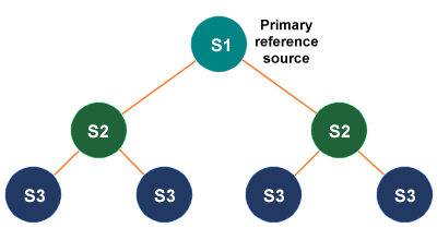
The SONET clock signal hierarchy
Clock signals are passed down from a primary reference source through the clock signal hierarchy. The clock signal received from a higher level by stratum 2 or stratum 3 is regenerated using digital phase-locked loops (DPLLs). If more than one source is available, the best quality clock signal is chosen by monitoring the synchronisation status messages (SSMs) located within the signal overhead of incoming signals. At the gateway between networks that have independent clock sources, network elements can compensate for minor variations in timing using pointer operations.
SONET network management
A telecommunications management network provides the facilities needed to configure the network, handle error conditions, and monitor network performance. These facilities will include an Operations System (OS) which is effectively the network management centre for the entire network, and agents that reside within the various network elements. SONET networks are commonly managed using the Transaction Language 1 (TL1) telecommunications management protocol. TL1 messages are exchanged between the operations systems that control the network, and the agents located within the SONET network elements using network management protocols such as the Control Management Information Protocol (CMIP) or the Simple Network Management Protocol (SNMP). Although some configuration of network elements may be carried out locally by "craftspersons" using a "craft interface" (essentially the issuing of configuration commands manually via a terminal), this is usually handled by a part of the network management system operating at a higher level. Typical configuration activities include the allocation of network bandwidth and software upgrades.
The management of SONET network elements is handled using data communication channels D1 to D3, part of the SONET section overhead, which between them have a data rate of 192 kbps (three 64 kbps channels). The remaining data communication channels (D4 to D12, included in the SONET line overhead) have a collective data rate of 576 kbps, and can be used for non-SONET specific purposes. Most network elements in a SONET network have a built-in router for routing network commands, and may use a range of network protocols for this purpose including IP and PPP. Network elements at each layer within the SONET network are responsible for monitoring the status of alarm and error information contained within the overhead bytes for that layer, and for responding to that information appropriately. Section terminating equipment (STE) monitors and responds to the performance indicators carried within the section overhead (SOH), for example. A number of alarm and error messages are built into SONET, and are known as defects and anomalies respectively. The term defect implies that a fairly serious error has been detected by a network element, such as a complete loss of signal (LOS). An anomaly, on the other hand, could arise due to the detection of a test sequence error (TSE) in data received (in other words, a parity error).
Parity checking occurs in each layer of the SONET overhead using bit interleaved parity (BIP). In the path layer, parity is calculated for the previous STS-N frame minus the transport overhead (TOH), and the resulting bit interleaved parity byte is stored in the B3 byte location of every STS-1 frame in the STS-N signal. Line layer parity is calculated for the previous STS-N frame minus the section overhead (SOH), and the resulting parity byte is stored in byte B2 of every STS-1 frame in the STS-N signal. Section layer parity is calculated for the entire previous STS-N frame, and the result stored in byte B1 of the first STS-1 of an STS-N frame. The bit parity calculation itself places a one in a particular bit position within the parity byte if there is an odd number of ones in that bit position in total for all of the bytes covered by the calculation. Otherwise, it places a zero in that bit position. Parity bytes are re-calculated at the receiver and compared with the transmitted parity bytes in order to determine whether or not an error has occurred in transmission.
Path, section or line terminating equipment detecting a bit error will transmit a remote error indication (REI) message to the point of origin (note that byte J1 in the path overhead is a path trace byte that carries a 64-byte ASCII string - one byte per STS-1 frame - that is assigned at the point of origin and carries information about the source of the path). In the more serious event of a complete loss of signal, traffic is re-routed over a backup connection and an alarm indication signal (AIS) is transmitted to downstream nodes in order to alert them to the problem. The receiver will inform the transmitter of the loss of signal condition by returning a remote defect indication (RDI). All of the alarm messages are transmitted in defined byte positions within the section, line and path overhead.
