| Author: | |
| Website: | |
| Page title: | |
| URL: | |
| Published: | |
| Last revised: | |
| Accessed: |
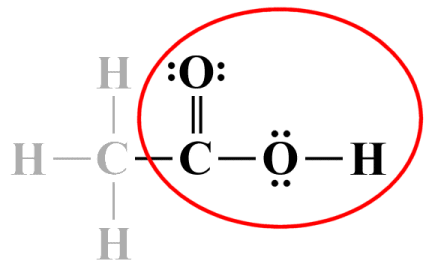
Lewis structures are relatively simplistic diagrammatic representations of how atoms and their valence electrons are arranged within a molecule. Each atom in a Lewis structure is represented by the one- or two-letter identification symbol used to identify its element in the periodic table. Covalent bonds are shown as single, double or triple lines connecting the atoms, with each line representing a pair of shared electrons (a pairs of dots can be used instead of a line, but we prefer to use lines). Lone valence electron pairs are shown as a pair of dots. The Lewis structure diagram for a carbon dioxide (CO2 ) molecule would look like this:
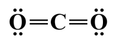
A Lewis structure diagram for a carbon dioxide (CO2 ) molecule
Lewis structures are named after the American chemist Gilbert N. Lewis (1875–1946), best known for his discovery of the covalent bond and for developing the concept of electron pairs. Lewis introduced the Lewis structure in his 1916 article "The Atom and the Molecule". As a two-dimensional representation of an essentially three-dimensional entity, a Lewis structure cannot adequately describe the geometry of a molecule. Nor does it attempt to explain how bonds form, or how valence electrons are shared between atoms.
What a Lewis structure can do is describe how valence electrons are distributed within a molecule, i.e. either as participants in a covalent bond or as lone electron pairs belonging to an individual atom. The diagram itself is generally required to obey something called the octet rule. This is a chemical rule of thumb that reflects the theory that main group elements bond in such a way that each atom is surrounded by eight valence electrons, essentially giving it a noble gas configuration.
Using the Lewis structure for CO2 (see above) as an example, we can see that the central carbon atom is involved in two double covalent bonds, each of which consists of four shared valence electrons. Each oxygen atom participates in one double covalent bond, and has two lone pairs of electrons. Thus, each atom in the CO2 molecule is surrounded by eight valence electrons, and the Lewis structure satisfies the octet rule. It is important to remember that the electrons shared by two atoms in a covalent bond are actually counted twice - once for each atom involved in the bond.
Despite what Lewis structures don't tell us about the characteristics of a molecule, they are still considered useful by scientists and those teaching the physical sciences because they do provide a reasonably accurate description of the electronic structure of many molecular and ionic systems. Be aware, however, that there are some systems for which Lewis structures may lead to erroneous inferences with regard to things like bond order, bond length, or magnetic properties. This may well be the case, for example, for molecules known to contain unpaired electrons.
Before we look at how to go about drawing the Lewis structure for a particular molecule, we should perhaps point out that Lewis structures can also be used to represent individual atoms, monatomic ions, polyatomic (or molecular) ions, and ionic compounds. The diagram below gives examples of how individual atoms of an element might be represented. Each element is represented by its one- or two-letter symbol, surrounded by some number of dots representing the valence electrons in its outer shell.
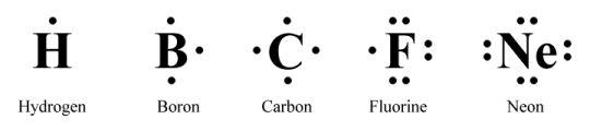
Lewis structures for atoms of various main group elements
There does not appear to be a specific set of rules with regard to the order in which the dots representing the valence electrons are drawn. One suggestion - and the method we have used here - is to imagine a square drawn around the symbol representing the atom and place one dot on each side of the square, starting at the top and moving clockwise, until all the valence electrons are used up. The only rule is that no more than two dots should appear on any one side.
Lewis structures can also be used to represent monatomic ions such as sodium (Na +) and chlorine (Cl -) ions, and polyatomic ions such as nitrate (NO3 -), phosphate (PO4 3-) and sulphate (SO4 2-). In such cases, in addition to showing how valence electrons are distributed, the Lewis diagram will show the charge on the ion.
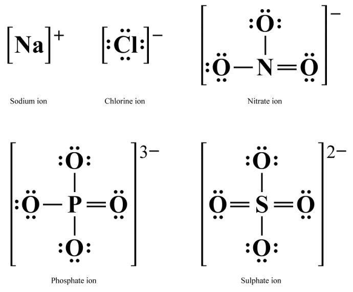
Lewis structures for various ions
As you can see, in Lewis structures for monatomic ions the chemical symbol for the element is surrounded by the number of valence electrons present in the ion, and the entire structure is placed within square brackets. The ionic charge is shown as a superscripted value to the right of the square brackets.
The Lewis structure for a polyatomic ion looks similar to that of any (non-ionic) molecule, with each atom represented by its chemical symbol, shared electron pairs represented by lines, and lone electron pairs shown as a pair of dots. However, as for monatomic ions, the entire structure is now enclosed within square brackets, and the ionic charge is shown as a superscripted value to the right of the square brackets.
Note that the number of electrons shown in the Lewis structure of a monatomic ion will be the number of valence electrons the atom would have if it were "neutral", i.e. not ionised, minus the value of the ionic charge. The same is true for a polyatomic ion except that this time the number of electrons drawn in the Lewis structure must equal the sum of the valence electrons normally associated with the participating atoms, minus the ionic charge (remember to take into account the sign of the charge when making these calculations).
There are two issues we must consider when drawing Lewis structures, especially those for polyatomic ions or molecules - which we will henceforth refer to as polyatomic species. The first concerns something called formal charge. The issue of formal charge arises when we compare the number of valence electrons around a "neutral" atom (i.e. an atom that is not involved in a chemical bond) with the number of valence electrons around an atom that is involved in one or more chemical bonds. The formal charge on each atom is calculated as the difference between these two numbers and is usually, though not always, an integer value (note that the relative electronegativities of the bonded atoms is not taken into consideration).
The second issue concerns something called resonance. When we set out to draw a Lewis structure, it will sometimes be the case that the structure can be drawn in two or more different ways for the same polyatomic species. As a general guideline, if you can draw two or more (legitimate) Lewis diagrams for the same molecule, the molecule itself will behave as the average of these structures. For this reason, each of the competing Lewis structures is called a resonance contributor.
We will be looking examples of how formal charges and resonance are handled in due course. First, we will outline some of the rules that apply to Lewis structures, and describe a basic step-by step process that you can use to draw one.
One of the most important rules to remember is the so-called octet rule, which as you may recall we made reference to earlier. This is a rule of thumb based on the assumption that, when atoms bond together to create a molecule, they do so in a manner that gives each atom eight electrons in its valence shell, thereby giving it the same electronic configuration as a noble gas.
The octet rule applies only to the s- and p-block elements (i.e., everything except the transition metals, which have their own 18-electron rule, which we'll briefly discuss elsewhere). The two exceptions are hydrogen and helium, both of which require only two valence electrons to have a complete outer shell. When counting electrons for the purpose of calculating formal charge, take into account all lone pairs, plus one electron for each covalent bond in which the atom participates. A single covalent bond thus contributes one electron, a double covalent bond contributes two electrons, and a triple covalent bond contributes three electrons.
Other guidelines to observe when drawing Lewis structures include the following:
Drawing a Lewis structure is often a matter of trial and error, depending on how much we already know about the polyatomic species we are trying to represent. In some cases, there are experimental data available from which we can infer much about molecular geometry, bond lengths, and so on. At other times, all we have to go on is a chemical formula. Assuming the latter to be the case, follow this step-by step process for drawing a Lewis structure:
Let's work through some examples to see how this actually works. We'll start with a really simple example - an oxygen (O2 ) molecule. The first thing to do is calculate how many valence electrons we have in total (note that we are dealing here with a molecule rather than an ion, so the overall charge will be zero):
| Oxygen (2) × 6: | 12 |
| Charge: | 0 |
| Total: | 12 |
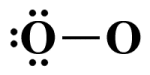
In this case, since we are creating a Lewis structure for a diatomic molecule consisting of two identical oxygen atoms, it is a simple matter to draw the basic skeletal structure:
The skeletal structure of an O2 molecule
The "central atom" in this case could be either of these two atoms, but for argument's sake we'll nominate the right-hand oxygen atom in the diagram for the role. Since we're treating the left-hand atom as a terminal atom, the next step is to complete its octet by adding lone electron pairs:
The terminal atom's octet is now complete
The next step is to complete the central atom's octet. Remember, we started with twelve valence electrons. So far, we have used two electrons for the single covalent bond and six more to complete the terminal atom's octet. We therefore have four electrons remaining:
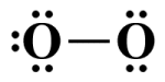
The central atom's octet is incomplete
We now have a problem because we have used our four remaining valence electrons but the central atom's octet is incomplete, breaking the octet rule. We solve the problem by taking one lone pair from the terminal atom in order to create a second covalent bond:
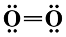
Adding a second covalent bond completes the central atom's octet
We need not concern ourselves with the formal charges on each atom here, because the twelve valence electrons are shared equally between the two oxygen atoms. When calculating formal charges, one electron from each shared (bonding) pair is allocated to each of the atoms participating in the bond. Thus, each atom is surrounded by six valence electrons - the same number of valence electrons they have in their unbonded state, giving a formal charge on each atom of zero.
Two nitrogen atoms will also bond to form a diatomic nitrogen (N2 ) molecule. This time, however, each atom has only five valence electrons. In order to obey the octet rule, each atom must share three valence electrons to form a triple covalent bond, leaving each nitrogen atom with a single lone pair.
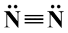
A triple covalent bond between two nitrogen atoms in an N2 molecule
We'll move on now to a couple of examples of more complex molecules. We've already seen the Lewis structure for a carbon dioxide (CO2 ) molecule, which consists of a central carbon atom bonded to two oxygen atoms. Carbon is an important component of many organic and inorganic compounds - indeed, carbon-based compounds form the basis of all life on Earth! We'll start with methane (CH4 ), a simple organic compound. The first task is to find the number of valence electrons available to us:
| Carbon (1) × 4: | 4 |
| Hydrogen (4) × 1: | 4 |
| Charge: | 0 |
| Total: | 8 |
Next, we draw the skeletal structure. Although hydrogen has a lower electronegativity than carbon, the rule is that hydrogen can only ever be a terminal atom, so the central atom here is carbon. The structure thus looks like this:
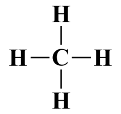
The skeletal structure of a CH4 molecule
As you can see, all of the available valence electrons are involved in single covalent bonds, so our Lewis diagram is complete. The central carbon atom is surrounded by eight valence electrons, so its octet is complete. The hydrogen atoms are each surrounded by two valence electrons, and since hydrogen is an exception to the octet rule, only requiring two valence electrons in its outer shell, it too has a stable configuration.
Once again, we need not concern ourselves with the formal charges on each atom because the carbon atom's share in the four single covalent bonds gives it four valence electrons – the same number of valence electrons it has in its unbonded state. The same applies to the hydrogen atoms, so the formal charge on each participating atom is zero (you will find this to be the case for the vast majority of molecules that do not carry an overall positive or negative charge).
We'll look now at how to draw the Lewis structure for a molecule of acetic acid (CH3 COOH). Also known as ethanoic acid, ethylic acid, or methane carboxylic acid, acetic acid is an organic compound produced as a byproduct of the fermentation process. You may well have come across acetic acid, since a common household product - vinegar - is essentially an aqueous solution containing approximately 5% acetic acid. Well start, as before, by finding the total number of valence electrons available to us:
| Carbon (2) × 4: | 8 |
| Oxygen (2) × 6: | 12 |
| Hydrogen (4) × 1: | 4 |
| Charge: | 0 |
| Total: | 24 |
Now we'll draw the skeletal structure. We know that hydrogen must always be a terminal atom, so the choice for the central atom is between carbon and oxygen. Since carbon has the lower electronegativity of the two, our central atom will be a carbon atom. The acetic acid molecule actually has two carbon atoms, but we'll nominate the carbon atom that appears first in the formula, which indicates that this atom is bonded to three of the hydrogen atoms.
The way the formula is written also seems to indicate that the two carbon atoms share a bond. The second carbon atom is followed in the formula by two oxygen atoms. We have already seen that, with a few exceptions, an oxygen atom will not bond with another oxygen atom, so we can probably safely assume that each of the two oxygen atoms shares a bond with the second carbon atom. The final inference from the formula is that the last hydrogen atom is bonded to the second hydrogen atom. Our skeletal Lewis structure thus looks like this:
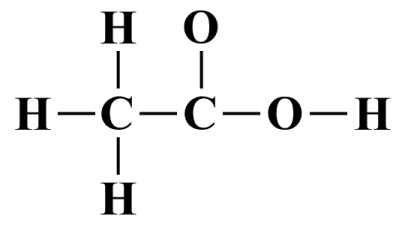
The skeletal structure of a CH3 COOH molecule
There are seven single covalent bonds in this structure, which accounts for fourteen of the twenty-four available valence electrons. We therefore have ten valence electrons that must be allocated as lone pairs. All of the hydron atoms have complete outer shells by virtue of the fact that they all participate in a single covalent bond. We'll allocate the rest of the available valence electrons to the remaining outermost terminating atoms (the two oxygen atoms, which are also the most electronegative atoms), which will complete the octets for these atoms:
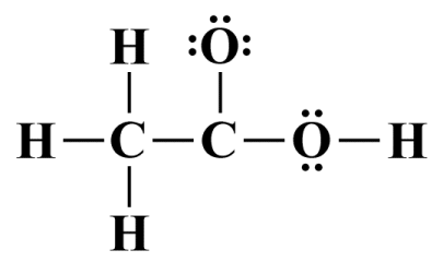
All of the valence electrons have now been accounted for
We are almost finished, but a quick tally will show that the second carbon atom does not have a complete octet. We will remedy this by taking one lone pair from the first oxygen atom in order to create a second covalent bond between it and the second carbon atom:
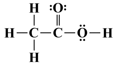
A double covalent bond will complete the second carbon atom's octet
Once again, we do not need to worry about formal charges - the formal charge for every atom in the molecule evaluates to zero. On a side note, the group to the right of the central carbon atom is a relatively common functional group (COOH). A functional group is a group of atoms within a molecule that has similar chemical properties whenever it appears in a chemical compound, even if other parts of the molecule are very different. Knowledge of this kind can make life much easier when you have to draw a Lewis diagram. For example, whenever you see COOH, you know it's always going to look like it does in the Lewis diagram we just drew:
Functional groups like COOH always have similar chemical properties
Not all molecules obey the octet rule. It is quite possible for a molecule to be electronically neutral overall, but contain atoms that, for one reason or another, cannot achieve eight electrons in their outer shell. Let's look at an example, the simple inorganic compound nitric oxide (NO) - a colorless gas composed of a single nitrogen atom and a single oxygen atom. Nitric oxide is one of the principal oxides of nitrogen, and one of the main components of acid rain. Nitric oxide is also a free radical because it contains an unpaired valence electron, which makes it very reactive. Let's try drawing the Lewis structure for nitric oxide. We start by counting the valence electrons:
| Nitrogen (1) × 5: | 5 |
| Oxygen (1) × 6: | 6 |
| Charge: | 0 |
| Total: | 11 |
You can probably spot the problem here right away, which is that the molecule has an odd number of valence electrons. Each covalent bond requires two valence electrons, as does each lone pair, so regardless of how many covalent bonds versus lone pairs we actually end up with, there will inevitably be one unpaired electron. It simply isn't possible under these circumstances for both atoms to be surrounded by eight valence electrons. Drawing the skeletal structure is a relatively trivial exercise:
The skeletal Lewis structure for NO
Two valence electrons are required for the single covalent bond, which leaves us with nine valence electrons - four lone pairs plus a single unpaired electron. We'll distribute these remaining valence electrons, starting with the oxygen atom which, as the most electronegative atom, fills the role of the sole terminating atom:
All of the valence electrons are accounted for
The oxygen atom now has eight electrons in its outer shell, but the nitrogen atom only has five. We can improve on the situation by taking two of the valence electrons from the oxygen atom to create a second covalent bond. The oxygen atom will still have eight electrons in its outer shell, but the nitrogen atom now has seven, although this is still one short of the eight required to satisfy the octet rule. It does mean, however, that the formal charges on both atoms will be zero, indicating that this is the most stable structure. Here is the completed Lewis structure for NO:
The completed Lewis diagram for NO
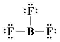
The octet rule can also be broken when there are simply too few valence electrons. One example of a compound in which this occurs is boron trifluoride (BF3 ), a colourless gas with a strong odour that forms dense white fumes in moist air. A BF3 molecule consists of a single boron atom covalently bonded to three fluorine atoms. We'll follow the usual steps for creating the Lewis structure, starting with the valence electron count:
| Boron (1) × 3: | 3 |
| Fluorine (3) × 7: | 21 |
| Charge: | 0 |
| Total: | 24 |
Next, we draw the skeletal structure. The central atom will be boron which has a lower electronegativity than fluorine:
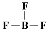
The skeletal Lewis structure for BF3
The three single covalent bonds take up six of the available valence electrons. We will distribute the remaining eighteen electrons to the fluorine atoms to complete their octets:
The completed Lewis structure for BF3
Each fluorine atom now has a complete octet. The boron atom, however, has only six electrons in its outer shell, breaking the octet rule. Nevertheless, a quick calculation shows us that the formal charge on each atom is zero, leading to the conclusion that this is the most stable configuration. Experimental data indicates that this is indeed the case. Stable compounds with incomplete octets due to an electron deficit are relatively uncommon, and are found only in some compounds of boron, beryllium and aluminium.
We could use a lone pair to create a double covalent bond between the boron atom and one of the three fluorine atoms, which would enable the boron atom to complete its octet. However, this would give the boron atom a formal charge of -1, and the double bonded fluorine atom a formal charge of +1, which suggests a less stable molecular structure than we already have. It also violates the principle that negative formal charge should preferentially reside on more electronegative atoms. Not only is fluorine significantly more electronegative than boron, it is the most electronegative element in the entire periodic table!
The possibility of having too many valence electrons does not arise in the first two periods of the periodic table. The period one elements, hydrogen and lithium, both have a single s orbital and require just two valence electrons for a full outer shell. The period two and three elements have a single s orbital and three p orbitals in their outer shell. Each of these orbitals can hold two electrons, so an element belonging either of these periods would appear to be restricted to a maximum of eight valence electrons. Whilst this is certainly true for period two, the picture for period three is somewhat different, as we shall see.
In the first two elements of period four (potassium and calcium) the 4s orbital is again filled first. For the next ten elements of period four, however, we see the five 3d orbitals being filled. These elements are part of a group known as the d-block elements, also known as transition metals because they have an inner electron shell that is in the process of transitioning between a stable configuration of eight electrons and one of eighteen electrons, or between a stable configuration of eighteen electrons and one of thirty-two electrons.
The important thing to note here is that even though we normally only consider the s and p orbitals when writing the electronic configuration for atoms of period three elements, the valence shell is the third energy level (n = 3), which means that d orbitals are available, even if they are empty. The significance of this becomes apparent when we start looking at compounds involving elements of period three and above. To illustrate what we mean, we will draw the Lewis structure for phosphorus pentachloride (PCl5 ). First, we'll count the valence electrons:
| Phosphorus (1) × 5: | 5 |
| Chlorine (5) × 7: | 35 |
| Charge: | 0 |
| Total: | 40 |
Next, we'll draw the skeletal structure. As the least electronegative atom, phosphorus will be the central atom, surrounded by the five chlorine atoms:
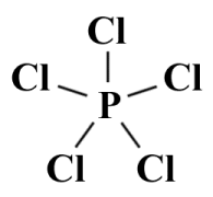
The skeletal Lewis structure for PCl5
Ten of the forty available valence electrons are taken up by the five single covalent bonds. We'll distribute the remaining thirty electrons to the chlorine atoms to complete their octets:
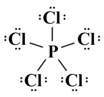
The completed Lewis structure for PCl5
Since each of the five chlorine atoms requires three lone pairs in order to complete its octet, we have now used all of the remaining valence electrons (thirty in total). The central phosphorous atom participates in five single covalent bonds and thus has ten electrons in its outer shell. The formal charges on all of the participating atoms turns out to be zero, so we can assume that this is a stable arrangement, but we have once again broken the octet rule, this time by having two valence electrons too many around the central atom. The single 3s orbital and the three 3p orbitals can hold a total of eight electrons between them, so what happens to the two extra electrons?
The generally accepted explanation is that elements of periods three and beyond can use their d orbitals to hold bonding electrons, allowing the valence shell of an atom to be expanded in order to accommodate more than eight valence electrons. You may see the term expanded octet used to describe a valence shell that exceeds eight electrons, although we find this to be somewhat of a misnomer, since if the valence shell has more than eight electrons it is not an octet. We prefer to use the term hypervalent to refer to a valence shell with more than eight valence electrons.
We have already seen how to calculate the formal charges on a bonded atom. We also know that for the majority of (uncharged) molecules, the formal charges on each atom will usually be zero. Indeed, none of the Lewis structures we have drawn for uncharged molecules up to this point have included formal charges because all of the participating atoms have a formal charge of zero. The structures are electronically stable and have their lowest possible energy level. There are occasions, however, when it is not possible to draw a Lewis structure in which all, or even most of the atoms have a zero formal charge.
It probably goes without saying that when we draw the Lewis structure for a polyatomic species that carries a positive or negative charge, there will always be at least one atom that carries a non-zero formal charge. It will also sometimes be the case that when we draw the Lewis structure for an otherwise electronically neutral polyatomic species, we will find that two or more atoms carry positive and negative formal charges.
Adding formal charges is always the final step when drawing a Lewis structure, because it is only after we have determined the order of each bond and allocated lone pairs that we can calculate the total number of electrons formally assigned to each atom. We can then compare this number to the number of electrons the atom would have in its unbonded (neutral) state. The rules for assigning electrons to an atom are fairly straightforward:
If the bonded atom has more valence electrons than the neutral atom, it carries a negative formal charge; with less valence electrons, it has a positive formal charge; and if the number of valence electrons remains the same, the formal charge is zero. The formula for calculating the formal charge on an atom is as follows:
FC = Ve - Ne - ½ Be
where:
FC is the formal charge on the atom
Ve is the number of valence electrons on the unbonded (neutral) atom
Ne is the number of non-bonding electrons allocated to the atom
Be is the total number of bonding electrons shared by the atom
Let's look at a couple of examples. We'll start by deriving the Lewis structure for the nitrate ion (NO3 -) that we saw earlier. Nitrates are found in many common fertilizers and explosive substances, and a nitrate ion is formed by the loss of a proton from a nitric acid (HNO₃ ) molecule. The number of valence electrons in a nitrate ion is calculated as follows:
| Nitrogen (1) × 5: | 5 |
| Oxygen (3) × 6: | 18 |
| Charge: | 1 |
| Total: | 24 |
In the skeletal structure nitrogen, as the least electronegative atom, will be the central atom:
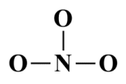
The skeletal structure of the NO3 - ion
Six of the twenty-four valence electrons are involved in covalent bonding, leaving eighteen unallocated. We can place these electrons on the oxygen atoms as follows:
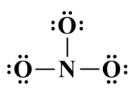
All valence electrons have been distributed
As you can see, each oxygen atom now has a complete octet, but the nitrogen only has six valence electrons in its outer shell. We can remedy this by taking two valence electrons from one of the oxygen atoms to create a double covalent bond between it and the central nitrogen atom, completing the nitrogen atom's octet (note that the choice of which oxygen atom to take the lone pair from is purely arbitrary - we'll be looking at the implications of this in due course):
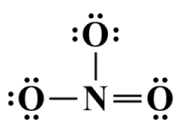
Each atom now has a complete octet
In the simplified representation of this ion, which we saw earlier, we placed the entire structure inside square brackets, and showed the overall charge as a superscripted value to the right of the square brackets. Once you become familiar with Lewis structures you will find this kind of representation perfectly adequate. Sometimes, however, you might wish to present a more detailed breakdown. Here are two alternative Lewis structures for NO3 -:
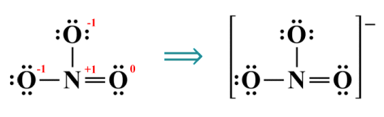
Complete (left) and simplified (right) Lewis structures for the nitrate ion
The sum of the formal charges on all of the atoms in a polyatomic ion should of course equal the overall charge on the ion itself (the formal charges in a neutral molecule must always sum to zero). The guiding principle when drawing a Lewis diagram is to find the most stable electronic configuration, which means that as many of the atoms as possible should have a formal charge of zero. Wherever possible, negative charges should appear on the most electronegative atoms and positive charges should appear on the least electronegative atoms.
Almost without exception, a single covalent bond between two atoms is created by the head-to-head overlap of two (half-filled) s orbitals, two p orbitals, or an s and a p orbital. We call this type of bond a sigma (σ) bond, and it is the strongest type of covalent bond.
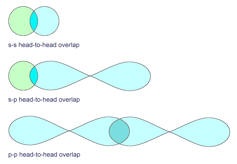
Three different types of sigma bond
The other kind of bond found in covalent structures is called a pi (π) bond, formed from the side-to-side (lateral) overlap of two half-filled p orbitals. Pi bonds are found in double and triple covalent bonds. A double covalent bond consists of a sigma bond and a pi bond, while a triple covalent bond consists of a sigma bond and two pi bonds. Note that pi bonds only occur in combination with a sigma bond. A typical double covalent bond is illustrated below.
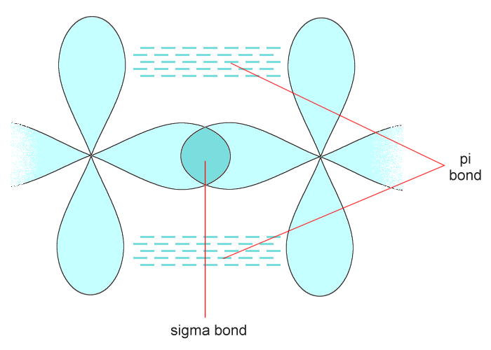
A typical double covalent bond
It is sometimes possible to draw two or more legitimate Lewis structures for the same polyatomic species, in which case each of those Lewis structures is called a resonance structure. Let's look at an example: the simple inorganic compound nitrous oxide (N2 O) - otherwise known as laughing gas. Nitrous oxide is a non-metal nitride, i.e. an inorganic compound of nitrogen and one or more atoms belining to the group known as "other non-metals" - elements that lie between the metalloids and the halogens in the periodic table (the group includes carbon, nitrogen, oxygen, phosphorous, sulphur and selenium). We start as usual by finding the total number of valence electrons:
| Nitrogen (2) × 5: | 10 |
| Oxygen (1) × 6: | 6 |
| Charge: | 0 |
| Total: | 16 |
Now we draw the skeletal structure. The central atom will be a nitrogen atom, because nitrogen is less electronegative than oxygen (3.04 for nitrogen as compared with 3.44 for oxygen):
The skeletal structure of an N2 O molecule
As we can see, there is a single bond between the two nitrogen atoms and another single bond between the central nitrogen atom and the oxygen atom. Four of our sixteen valence electrons have therefore been spoken for, leaving twelve still to be allocated. Let's allocate the remaining valence electrons now:
The remaining valence electrons have been allocated
The terminal nitrogen and oxygen atoms now have complete octets, but the central nitrogen atom only has four electrons in its valence shell. It will need two additional covalent bonds in order to complete its octet, which means there are three possibilities. The first option is to take a lone pair from each of the terminal atoms in order to create two double bonds. Alternatively, we can take two lone pairs from the outer nitrogen atom to create a triple bond between it and the central nitrogen atom. The third option is to take two lone pairs from the oxygen atom and create a triple bond between it and the central atom. Our three candidate Lewis structures will therefore look like this:
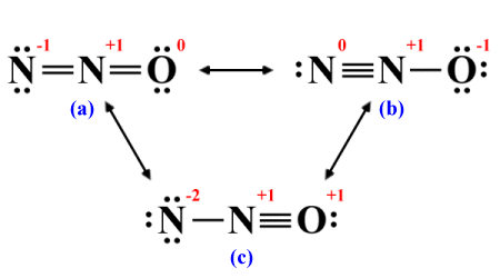
We can derive three possible structures
The two-way arrows in the diagram are used to indicate that the structures represent the same polyatomic species. If you study the diagram, you will see that in each of the structures we have drawn the atoms always occupy the same position. Once you have allocated the remaining valence electrons, you can explore the different ways in which these non-bonding electrons can be redistributed so that each atom has a complete octet, but the atoms themselves never move.
Which of these alternative Lewis structures, if any, accurately represents the electronic configuration of N2 O? If we can draw two or more alternative Lewis structures for the same polyatomic species, it is unlikely that any of them are completely reliable when it comes to predicting the electronic configuration of that polyatomic species.
One thing we can say in this particular instance is that the three structures are not equivalent, because the distribution of electrons in each case is different. We can see that the structures are different without going into a detailed analysis simply by looking at the formal charge on the oxygen atom in each case. This implies that the potential energy associated with each structure will also be different.
We can determine which Lewis structure is most likely to represent the electronic properties of N2 O by examining the formal charges for each structure. The most stable molecular configuration will be the one with the lowest potential energy, so we are looking for the Lewis structure with formal charges closest to zero. On that basis, we can immediately eliminate structure (c), because it gives one of the nitrogen atoms a formal charge of -2 and the other two atoms a charge of +1:
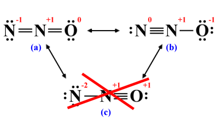
Formal charges should be as close to zero as possible
The remaining options look pretty much the same in that both structures have one atom with a formal charge of +1 and one atom with a formal charge of -1. However, we stated earlier that wherever possible, negative charges should appear on the most electronegative atoms and positive charges should appear on the least electronegative atoms. Of the two remaining options, only structure (b) meets this criterion because it has a formal charge of -1 on the oxygen atom and a formal charge of +1 on the neighbouring nitrogen atom:
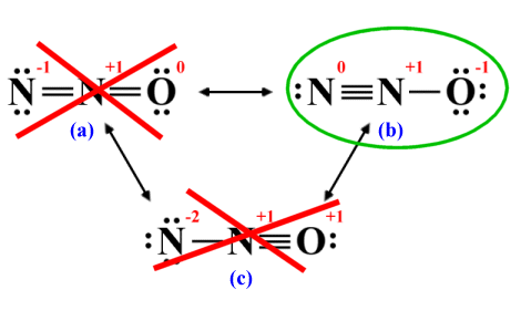
A negative formal charge should appear on the most electronegative atom
When some number of legitimate but non-equivalent Lewis structures can be drawn for the same polyatomic species, none of them will completely describe the electronic characteristics of that species. The reality is likely to resemble a hybrid of the possible structures, in which each structure is weighted according to the degree to which it represents a stable electronic configuration. Resonance structures that represent highly stable electronic configurations are said to be major contributors. Those that represent less stable electronic configurations are called minor contributors.
It is important to realise that there is only ever one real structure for a given polyatomic species. If some number of legitimate resonance structures - i.e. structures that obey the rules for resonance structures - can be drawn, then the real structure will be a hybrid of the individual resonance contributors. The resonance structures are simply different representations of the same polyatomic species, none of which are as stable as the real (hybrid) structure.
The contribution made by each resonance structure will be proportional to its stability. Unless all of the resonance structures are equivalent, the most stable resonance structure can usually be considered to best represent the polyatomic species' actual structure.
Before we go any further, here are a few rules we can apply for deriving a legitimate set of resonance structures for a polyatomic species:
Resonant structures are essentially alternative representations of the same polyatomic species. Since the actual structure of the species will be a hybrid of all the resonance contributors, none of the resonance structurers, including the most stable contributor, will fully represent that structure. This has important implications for the distribution of valence electrons within the molecule or polyatomic ion.
Different resonance structures are created by "moving" either lone pair electrons or π electrons (electrons involved in pi bonds) to an adjacent position. This apparent movement of electrons represents the fact that, in the hybrid structure, those electrons do not belong to a single atom or covalent bond. They are said to be delocalised.
As we have seen, resonance structures represent the delocalisation of valence electrons, which is often associated with a redistribution of charge. You will often see resonance structures in which curved arrows are used to highlight the difference between two or more resonance structures. Each arrow represents the "movement" of two π electrons that occurs when we transition from one resonance structure to another. Let's look at a couple of examples.
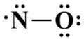
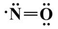
We'll start by looking at the resonance structures for nitrous acid (HNO2 ). The hydrogen atom cannot be the central atom so the nitrogen atom, with a lower electronegativity than oxygen, will occupy that role. As we have seen, oxygen atoms rarely bond with other oxygen atoms, so we have two possibilities for legitimate resonance structures:
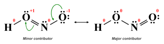
Resonance structures for nitrous acid (HNO2 )
Both of the structures we have drawn here conform to the guidelines for drawing Lewis structures in terms of obeying the octet rule (with the exception of the hydrogen atom) and having the same overall charge, but they are not equivalent. In the left-hand structure, one of the oxygen atoms has a single covalent bond with the hydrogen atom, a double covalent bond with the central nitrogen atom, and two lone pairs, giving it a positive formal charge of +1. The second oxygen atom has a single covalent bond with the nitrogen atom and three lone pairs, leaving it with a negative formal charge of -1.
In the right-hand structure, the first oxygen atom has single covalent bonds with both the hydrogen atom and the central nitrogen atom and two lone pairs, while the second oxygen atom now has a double covalent bond with the nitrogen atom and two lone pairs. The formal charge on all atoms in the structure is zero. Since the actual HNO2 molecule itself will most closely resemble the resonance structure with the fewest formal charges, it is reasonable to conclude that the right-hand structure is the major contributor.
The curved arrows indicate the movement of electrons that must take place in order for the left-hand structure (i.e. the minor contributor) to transition into the right-hand structure (the major contributor). We must emphasise here that, even though the molecule itself will more closely resemble the major contributor, the true structure of the molecule will be a hybrid of these two structures. So, what will it actually look like? Let's start by drawing the structure that would result by taking the average of these two structures, considering bond order only:
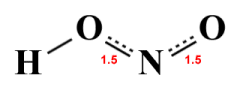
The average of the two HNO2 resonance structures
Given that the major contributor will, by definition, be more like the actual HNO2 molecule than the minor contributor, then we could reasonably expect that the true structure of the molecule will be somewhere in between the major contributor and the average structure we have drawn above, at least in terms of bond order. We could represent this as follows:
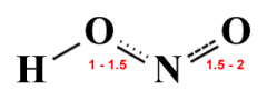
Relative bond orders in the HNO2 molecule
If the above diagram is a reasonably accurate representation of the HNO2 molecule, we can conclude that the delocalised π electrons participate in both N-O bonds. We could nevertheless also conclude that the right-hand N-O bond is significantly stronger than the left-hand N-O bond, in which case it should also have a shorter bond length. Experimental data for the NHO2 molecule gives a bond length of 120 picometres for the right-hand N-O bond and 146 picometres for the left-hand N-O bond, which would seem to support this conclusion.
Resonance can only occur in a polyatomic species that has at least one double (or triple) bond. A single covalent bond always consists of a single sigma bond involving the head-to-head overlap of s or p orbitals, in which the movement of the participating valence electrons is tightly restricted. Sigma bonds cannot easily be broken, and when they are it is invariably the result of a chemical reaction. Pi bonds, on the other hand, involve the lateral (sideways) overlap of p orbitals. The electrons in p orbitals are thus far more mobile. Lone pairs of electrons are also relatively mobile because they are not involved in bonding.
When a molecule can be represented by one or more resonance structures, a lone pair of electrons can be removed from an atom to form a pi bond between that atom and one of its neighbouring atoms. Movement in the other direction can also take place, whereby the electrons participating in a pi bond can be removed to form a lone pair on one of the atoms participating in the bond.
At this point we should emphasize once again that a molecule or polyatomic ion does not flip between one resonance structure and the next. We simply use resonance structures to visualise the possible electronic configurations of a polyatomic species and work out which of the possible structures most closely represents that species. If resonance structures can be drawn for a species, the structure of the species itself will resemble a hybrid of those resonance structures.
The significance of delocalised electrons is that they do not belong solely to one atom or to one covalent bond. They are distributed throughout the regions created by overlapping p orbitals, thereby reducing electron density and distributing the associated negative charge more evenly. The delocalisation of electrons thus enables a molecule or polyatomic ion to achieve a more stable electronic configuration.
If two or more resonance structures can be drawn for the same polyatomic species and all have the same formal charges and the same number of double covalent bonds, they are said to be equivalent. This being the case, each resonance structure makes an equal contribution to the resulting hybrid structure, which is then said to be an average of the contributing resonance structures. Let's look at a simple example to see how this works. We can draw the following resonance structures for the ozone (O3 ) molecule:
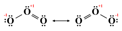
Resonance structures for ozone (O3 )
As you can see, each of the two resonance structures depicts the central oxygen atom as having a positive formal charge (+1). In each structure, one terminal oxygen atom shares a single covalent bond with the central atom and has a negative formal charge (-1), while the other shares a double covalent bond with the central atom and has a zero formal charge.
Given that we are dealing with three identical (oxygen) atoms, there is no obvious reason why one terminal atom should be more strongly bonded to the central atom than the other, or carry a different charge. If we assume that the actual molecule will indeed be a hybrid of the two resonance structures, then it will have two equal bonds, each with a bond order of 1.5 (in order to calculate the bond order of a specific bond in a hybrid structure, we simply add up the bond orders of that bond in all of the resonance structures and divide the result by the number of resonance structures).
We should also average the formal charges. The central atom in each case has a formal charge of +1, so the central atom in the hybrid will also carry a charge of +1. The left-hand terminal atoms in the two structures have charges of -1 and , so the left-hand terminal atom in the hybrid will carry a charge of -0.5. We get the same result if we average the formal charges in the two right-hand terminal atoms, so the right-hand terminal atom in the molecule will also carry a charge of -0.5. The resulting hybrid thus looks like this:
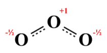
A hybrid structure for ozone (O3 )
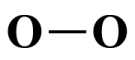
Chemical analysis reveals that both bonds in an actual O3 molecule are identical - they both have the same length and strength. The actual bond length is 127.2 picometres - shorter than a typical O-O single covalent bond (148 picometres) but longer than a typical O=O double bond (120.7 picometres). The central atom carries a positive charge, and both terminal atoms carry equal negative charges. The fact that both the bond order of each bond and the negative charge on each terminal atom are fractional is a clear indication of the involvement of delocalised electrons.
Note that the hybrid structure shown above is not a Lewis structure. A hybrid structure cannot be represented by a single Lewis structure because each atom in a legitimate Lewis structure must be involved in an integer number of covalent bonds, and carry an integer formal charge. Note the use of dashed lines to indicate the presence of fractional covalent bonds, which immediately tells us that the structure we are looking at is a hybrid structure.
We have drawn the O3 molecule's resonance structures - and the resulting hybrid structure - in the way we have because we know that the bond angle in an ozone molecule is 116.8 °. Molecular bond angles are dependent on the geometry of a molecular structure, which can be determined using a technique known as Valence Shell Electron Pair Repulsion (VSEPR) theory. Lewis structures on their own do not predict the geometry of a molecule, but they are a starting point for the VSEPR calculations (we will be looking at the topic of VSEPR in more detail elsewhere in this section).
Another very good example of resonance can be found in the benzine molecule, which is formed from six carbon atoms and six hydrogen atoms and has the chemical formula C6 H6 . Benzine is important in organic chemistry because it is a critical component of many common organic compounds, including those found in petroleum products, plastics, and synthetic fibres.
The six carbon atoms in the benzine molecule are connected by covalent bonds to form a planar hexagonal ring, with each carbon atom forming a separate covalent bond to one of the hydrogen atoms. Organic compounds based on the benzine ring are often referred to as aromatic compounds. The name originally came about because many of these compounds have a sweet fragrance, as does benzine itself. Today, however, it is used to refer to any organic compound that contains one or more carbon ring. The resonance structures for benzine are shown below.
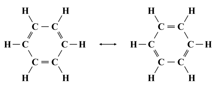
Resonance structures for benzine (C6 H6 )
The two resonance structures shown are equivalent. Each has the same formal charges (all atoms have a formal charge of zero) and the same number of double covalent bonds. However, neither structure is truly representative of the actual benzine molecule. We know from chemical analysis that the bond lengths of the six carbon-carbon bonds in benzine are identical (139.9 pm, as opposed to 154 pm for a typical C-C bond and 134 pm for a typical C=C bond), so a pattern of alternating single and double covalent bonds simply doesn't reflect the reality. The true structure of the benzine molecule is a hybrid of the two resonance structures in which each of the carbon-carbon bonds has a bond order of 1.5, as illustrated below.
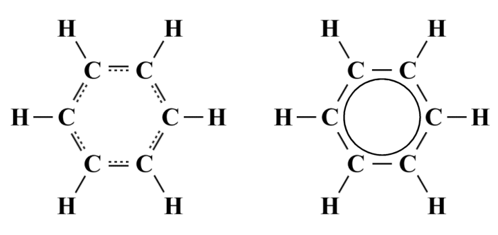
Alternative representations of the hybrid structure of benzine
Here we see two alternative methods of representing the benzine structure. The representation on the left uses dashed lines to indicate the presence of partial covalent bonds and show that the structure we are looking at is a hybrid structure. The alternative representation on the right can also be used to conveys the same information, and replaces the dashed lines with a circle drawn inside the hexagonal structure.
Even though the formal charge on each atom has not changed (each atom still has a formal charge of zero), the hybrid structure is more stable than either of the two resonance structures because the negative charges on the valence electrons are now evenly distributed amongst the six carbon atoms, thanks to the delocalisation of the valence electrons involved in the pi bonds.
This distribution of charge gives the benzine molecule its lowest possible potential energy and, together with the molecule's geometry, makes it very stable. It is worth noting here that, for any polyatomic species that exhibits resonance, the difference between the potential energy of the hybrid structure and the potential energy of the most stable contributing structure is known as the resonance energy (or delocalisation energy).
We will look at one final example of a species that has equivalent resonance structures, namely the nitrate (NO3 -) ion, which we looked at earlier. In our earlier examination, we presented a single Lewis structure that does not reflect what we actually know about the geometry of this particular species, i.e. that it has a trigonal planar structure with bond angles of 120°. For the sake of simplicity, we also ignored that fact that the nitrate ion exhibits resonance. It is in fact possible to draw three equivalent resonance structures for NO3 -, as shown below.
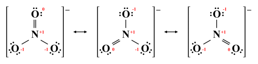
Resonance structures for the nitrate ion (NO3 -)
All three resonance structures are legitimate. The octet rule is satisfied for each atom, and negative and positive charges are allocated as we would expect, given the relative electronegativities of oxygen and nitrogen. In each structure, the nitrogen atom has a formal charge of +1, two of the oxygen atoms have a formal charge of -1, and one oxygen atom has a formal charge of zero, giving each structure the same overall charge. The number of single (sigma) and double (pi) bonds is also the same, so these three structures are equivalent - it doesn't matter which of the three oxygen atoms is double bonded to the central nitrogen atom.
Although all three resonance structures are equally stable, the nitrate ion itself bears a closer resemblance to the hybrid structure shown below. As previously, the hybrid structure is arrived at by averaging out the bond orders and formal charges of the three resonance structures. Negative charges are now distributed equally between the three oxygen atoms, and each N-O bond now has a bond order of 1 1/3 . This bond order is consistent with the observational data, i.e. that the bonds are of equal length and are also slightly shorter than a typical single covalent N-O bond. The observed three-way symmetry of the ion also suggests that this is the case.
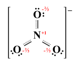
The hybrid structure of the nitrate ion