| Author: | |
| Website: | |
| Page title: | |
| URL: | |
| Published: | |
| Last revised: | |
| Accessed: |
A simple diatomic molecule consisting of two atoms of the same element will always have a linear geometry. The diatomic oxygen (O2 ) molecule is non polar because the two oxygen atoms have the same electronegativity, and there are no partial charges on either atom. As a result, the O2 molecule has zero dipole moment. A hydrogen fluoride (HF) molecule, on the other hand, has a strong dipole moment because fluorine - the most electronegative element in the periodic table - has an electronegativity of 3.98 compared with a value of 2.20 for hydrogen. And yet the hydrogen fluoride also has a linear geometry, because there is simply no other way to arrange two atoms.
The situation changes when a molecule consists of more than two atoms. Carbon dioxide (CO2 ) and water (H2 O) are both molecular substances, each of which has a molecular structure consisting of a single atom of one element covalently bonded to two atoms of another element, but they have different geometries. The CO2 molecule has a linear geometry, while the H2 O molecule is said to be bent, forming a broad V-shape with the oxygen atom at its vertex. Let's start by looking at the Lewis structure diagrams for these two molecules:
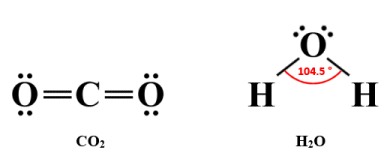
Lewis structure diagrams for CO2 and H2 O
The electrical configuration of a molecule has implications for its geometry, and vice versa. In the carbon dioxide molecule, the central carbon atom is surrounded by eight valence electrons, all of which are involved in bonding because there are two double covalent bonds. The negative charges in those double covalent bonds repel each other, which means that the oxygen atoms end up on opposite sides of the central carbon atom. The result is a linear molecular geometry in which the negative charges are evenly distributed. The carbon dioxide molecule is thus non-polar, having no overall dipole moment.
In the H2 O molecule, the central oxygen atom is also surrounded by eight valence electrons. This time, however, only four of those valence electrons are involved in bonding, because each hydrogen atom can only form a single covalent bond (i.e., a sigma bond) with the central oxygen atom. The remaining four valence electrons form two lone pairs. The negative charges on these lone pairs repel both each other and the negative charges on the single covalent bonds, creating a tetrahedral electron geometry (as opposed to molecular geometry) in order to get as far away from each other as possible.
Because there are only three atoms in the H2 O molecule, they will all lie in the same plane, but thanks to the tetrahedral electron geometry, there will be a nominal bond angle of 109.5°. In fact, because the lone pairs exert a stronger force of repulsion than the bonding pairs, the bonds are pushed closer together, and the actual bond angle is 104.5° - slightly less than the nominal bond angle.
This article is primarily concerned with the use of the VSEPR (Valence Shell Electron Pair Repulsion) model to predict the molecular geometry of a molecule, whereby we examine the arrangement of ligands (terminal atoms) around the central atom. Electron geometry is an alternative technique that focuses on how the electrons that surround the central atom are arranged, and will often (though not always) predict a shape that differs from that predicted by VSEPR for the same molecule. We just need to be aware of the distinction between electron geometry and molecular geometry in order to avoid any confusion.
Valence shell electron pair repulsion (or VSEPR) theory is a theoretical model used by physicists and chemists to predict the three-dimensional molecular geometry of polyatomic species (i.e., species consisting of three or more atoms) based on the number of valence shell electron pairs surrounding the central atom of a molecule or polyatomic ion. The model was originally proposed in 1939 by the Japanese chemist Ryutaro Tsuchida (1903-????) and was the subject of a 1940 Bakerian lecture given by the British chemists Nevil Vincent Sidgwick (1873-1952) and Herbert Marcus Powell (1906-1991). The theory was further developed and published in 1957 by the British chemist Ronald James Gillespie (1924-2021) and Australian chemist Ronald Sydney Nyholm (1917-1971).
The VSEPR model is based on the assumption that the negative charges on the valence electron pairs surrounding the central atom of a molecule or polyatomic ion (we often just refer to them collectively as polyatomic species or just species) - whether lone pairs or bonding pairs - will repel each other, and will arrange themselves within the species in order to minimise that repulsion. Putting it another way, they will get as far away from each other as possible. VSEPR is thus able to predict the geometry of the species by arranging the atoms so as to minimise the electrostatic repulsion between valence electron pairs, and thus reduce the overall energy of the species to its most stable state.
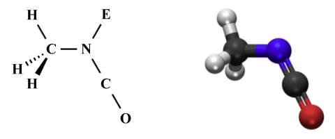
For the purposes of this discussion, the central atom (or in some cases atoms, plural) can be defined as an atom that is bonded to two or more other atoms, while a terminal atom is bonded to only one other atom. In the carbon dioxide (CO2 ) molecule, for example, the carbon atom is the central atom and the two oxygen atoms are terminal atoms. As a somewhat more complex example, we could look at methyl isocyanate (C2 H3 NO), in which the two carbon atoms and the nitrogen atom are the central atoms, while the three hydrogen atoms and the oxygen atoms are terminal atoms, as shown in the Lewis structure diagram below.
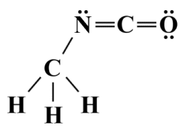
A Lewis structure for methyl isocyanate (C2 H3 NO)
We have discussed Lewis structures in some detail in the article "Lewis Structures" in this section, in which we stated that Lewis structures alone cannot predict the geometry of a polyatomic species. Nevertheless, drawing a Lewis structure is a useful first step in the VSEPR process because it enables us to determine the number of bonding and lone pairs around the central atom of a species. From this, we can determine something called the steric number - the sum of the number of atoms bonded to the central atom (called its coordination number) and the number of lone pairs formed from its non-bonding valence electrons. Here is the Lewis structure diagram for sulphur tetrafluoride (SF4 ):
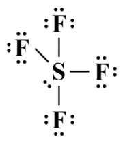
A Lewis structure for sulphur tetrafluoride (SF4 )
As you can see from the diagram, the central sulphur atom is bonded to four terminal (fluorine) atoms, and has a single lone pair of valence electrons. Its steric number is therefore 4 + 1 = 5. Note that the Lewis diagram itself is a strictly two-dimensional representation of the SF4 molecule, and as such tells us very little about its three-dimensional geometry. But what is the significance of the steric number?
Essentially, although we have been referring to the valence electron pairs involved in bonding as "bonding pairs" up to this point, the VSEPR model does not distinguish between single, double or triple covalent bonds. It would therefore be more accurate to refer to them as bonding groups. Henceforth, we will use the term "bonding group" to refer to all of the electrons involved in a bond between two atoms regardless of whether it is a single, double or triple covalent bond. Lone pairs are also considered to be "groups" in this context, as are unpaired electrons.
One question that often arises with respect to Lewis structures is: "How do we deal with resonance structures when applying the VSEPR model to a polyatomic species?". The short answer is that, whilst resonance is obviously an important consideration when you want to accurately determine the electronic configuration of a species, it does not significantly affect the shape of the species. Whichever resonance structure you select, it will not affect the number of electron groups surrounding the central atom (i.e., the steric number).
The bonding groups, lone pairs, and unpaired electrons (if any) surrounding the central atom of a polyatomic species are all assumed to lie on the surface of a sphere representing the valence shell. The sphere has the central atom at its centre, and the various electron groups, which we will refer to henceforth as domains, are predicted to occupy positions on the surface of the sphere such that they will be as far away from one another as possible, thus minimising the forces of repulsion they exert on each other. The steric number represents the total number of domains on the surface of the sphere, and will be a factor in determining the geometry of the polyatomic species.
The degree to which two domains repel each other will vary, depending on the precise nature of each domain, which will determine how much space they occupy within the polyatomic species. Non-bonding domains, i.e., those formed by a lone pair of valence electrons, are closer to the nucleus of the central atom and occupy more space in its valence shell than bonding domains, i.e., the domains created by electron groups involved in single, double or triple covalent bonds.
We can further classify a bonding domain according to the number of electron pairs involved in the bond. Thus, a single covalent bond is a one-electron-pair domain, a double bond is a two-electron-pair domain, and a triple bond is a three-electron-pair domain. The size of bonding domains will thus increase in accordance with bond order. Keep in mind however that, in the VSEPR model, we disregard bond order when deriving the steric number.
Another factor that will determine the size of the bonding domain is the electronegativity of the ligand (in this context, a ligand is an atom that is bonded to the central atom). The higher the electronegativity of the ligand, the greater the attractive force it will exert on the shared electrons, pulling them away from the central atom's nucleus and reducing the amount of space occupied by the domain within the central atom's valence shell.
In addition to the factors described above, the degree of repulsion between two electron domains can be ordered from highest to lowest as follows:
Differences in the degree of repulsion exhibited by the various domains within a species mean that in many cases the actual three-dimensional geometry of the species will differ slightly from that predicted by the VSEPR model. The H2O molecule we saw earlier provides a good example of this. With four domains in its valence shell, the electron geometry of the H2O molecule is determined to be tetrahedral, which means that we could expect the bond angle between the two O-H bonds to be 109.5°. However, the two lone pairs exert a greater mutual repulsion than the two bond pairs, resulting in a slightly smaller bond angle than expected of 104.5°.
Many sources that deal with molecular geometry use the terms "axial" (or "apical") and "equatorial" in relation to the position of one or more terminal atoms relative to a central atom. We can visualise the difference by imagining that a molecule is constructed within a three-dimensional coordinate system in which a vertical axis is bisected at 90° by a horizontal plane (we refer to this as the equatorial plane).
Ligands that lie above and below the horizontal plane on the vertical axis are said to occupy axial positions, while those that occupy positions within the equatorial plane around the vertical axis occupy equatorial positions. The central atom lies at the intersection of the vertical axis and the equatorial plane.
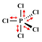
For some molecules, the distinction between axial and equatorial ligands is fairly easy to determine. Consider, for example, the phosphorous pentachloride (PCl5) molecule represented below. VSEPR predicts a trigonal bipyramidal geometry (we'll be looking at the nomenclature used for molecular geometries shortly), in which five chlorine atoms surround a single central phosphorous atom.
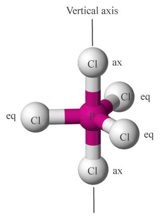
Chlorine atoms in PCl5 occupy axial (ax) or equatorial (eq) positions around the central phosphorous atom
It is not always immediately clear which ligands in a given molecular geometry occupy axial positions and which are equatorial. As a general rule of thumb, if three or more ligands lie in the same plane together with the central atom, they are considered to occupy equatorial positions. Two ligands that lie on opposite sides of the central atom on an axis that bisects the central atom, and that do not share a plane with any other ligands, are considered to be axial ligands.
Although the VSEPR model is relatively successful in predicting the molecular geometry of many polyatomic species, it has a number of limitations which we will discuss in more detail at the conclusion of this article. It does not, for example, take the relative atomic size of the ligands into account. This will have no effect on overall geometry, especially if the ligands are all atoms of the same element, but it could have an effect on bond angles if they are not. The same can be said of the effect of unpaired electrons, which for simplicity's sake are treated by VSEPR as if they were lone pairs.
VSEPR structures can be represented using two dimensional diagrams, but these diagrams are often accompanied by a three-dimensional ball-and-stick graphic. The three-dimensional ball-and-stick graphic can give us a good idea of the molecular geometry of a species, but it does not tell us much about the distribution of electron domains. The two-dimensional VSEPR diagram, on the other hand, gives us more complete information in this respect, but is not as intuitive when it comes to visualising molecular geometry. It is therefore common to see both methods used to represent the structure of polyatomic species. Here are three ways of representing the phosphorus pentachloride (PCl5 ) molecule:
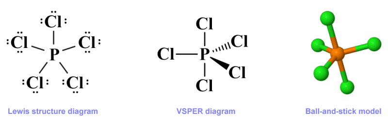
Three representations of the phosphorus pentachloride (PCl5 ) molecule
Like the Lewis structure diagram, the VSEPR diagram is purely two-dimensional. However, VESPR uses something called a perspective drawing to represent the three-dimensional nature of a molecule on a drawing surface, whether that surface is paper or a computer screen. As with the Lewis diagram, a line is drawn to connect the central atom to each terminal atom, but the nature of the line used in each case will depend on the spatial relationships between the atoms within the molecule rather than on bond order.
The overall direction of a connection, using the central atom as the starting point, is shown using different kinds of line. A plain solid line denotes a connection that lies in the plane of the drawing surface. A solid elongated wedge-shaped line indicates a connection that extends away from the plane of the drawing surface and towards the observer. A hatched elongated wedge-shaped line (or sometimes a thick dashed line) shows a connection that extends away from the observer, beyond the plane of the drawing surface.
Each of these three diagram types - Lewis structure diagram, VSEPR (perspective) diagram, and ball-and-stick model, gives us some information about a polyatomic species. The Lewis structure diagram is generally more informative when it come to the overall electronic configuration of a molecule. The ball-and-stick model provides a good visual representation of the species' molecular geometry but does not (usually) reveal much about its electronic configuration. The VSEPR diagram is not so intuitive visually, but when correctly interpreted gives us a good idea of both the overall shape of a species and important aspects of its electronic configuration.
The VSEPR diagram does not tell us about things like bond length or bond strength. Nor does it give us precise values for bond angles. In order to obtain accurate estimates for these characteristics, we have to do some additional work. The techniques used to obtain this information will be discussed elsewhere.
Going back to our phosphorous pentachloride (PCl5 ) molecule, we should point out that PCl5 does not have a lone electron pair around its central atom. When lone pairs are present, however, they play a critical role in determining the molecule's shape. We can think of a species as having either a regular or irregular geometry depending on various factors, most important of which will be the presence or absence of one or more lone pairs around the central atom.
In a regular geometry, all of the bond angles will be the same, whereas in an irregular geometry the bond angles will differ. Differences in bond order alone will certainly have some influence on bond angles, and even more so on bond length, but will not change the overall molecular geometry of a species. The presence of one or more lone pairs, on the other hand, will have a part to play in determining both the molecular geometry and the values of individual bond angles.
In order to illustrate the effect that lone pairs have on molecular geometry, let's consider the chlorine pentafluoride (ClF5 ) molecule. Chlorine pentafluoride is an interhalogen compound that, on the face of it, might seem like it should have a similar molecular geometry to phosphorous pentachloride, since it consists of a central chlorine atom surrounded by five identical (fluorine) atoms. Whereas PCl5 has a trigonal bi-pyramidal geometric structure, however, ClF5 adopts a square pyramidal shape, as illustrated below.
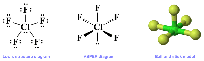
Three representations of the chlorine pentafluoride (ClF5 ) molecule
The Lewis structure shown here gives us all the information we need with regard to the distribution of the valence electrons in ClF5 , but does not tell us anything about the molecule's shape. The ball-and-stick model gives us a clear idea of the molecule's geometry, but tells us nothing about its electronic configuration. The VSEPR diagram, when correctly interpreted, tells us about the overall molecular geometry, i.e., that it has a square pyramidal shape. It also provides us with information about how the electron domains within the central atom's valence shell are organised.
Note that we have chosen to use a solid line here to represent the relationship between the central atom and its lone pair and to show that it lies in the plane of the drawing surface. The way in which lone pairs are represented in VSEPR diagrams varies from one source to another. In some they are represented simply as a pair of dots adjacent to the central atom. In others, a pair of dots adjacent to the central atom, and enclosed in a teardrop-shaped envelope.
We prefer the VESPR representation shown above because it provides more information about the orientation of the lone pair within the valence shell, relative to the central atom and the bonding domains (the two dots may be replaced by the letter "E", which reflects the AXE method, which we are going to look at shortly). For lone pairs that do not lie in the plane of the drawing surface we use the same line types that we use for covalent bonds. For example, here is our VSEPR diagram for a H2 O molecule:
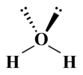
A VSEPR diagram for a H2 O molecule
The AXE method is used with the VSEPR model to formally specify the arrangement of domains around the central atom in a polyatomic species. The general form of the AXE formula for a species is AXm En , where A represents the central atom, X represents the ligands (i.e., the atoms bonded to A), and E represents the lone pairs around the central atom. The letters m and n represent the number of bonding domains and the number of lone pair domains respectively. H2 O, for example, has two ligands (the hydrogen atoms) and two lone pairs, so its AXE formula would be:
AX2 E2
The sum of the subscripts of X and E is the steric number, which for the H2 O molecule would be 4 (note that, unless otherwise specified, it is assumed that there is only one central atom, so A has an implied subscript of 1). The geometry of a species for a given AXE formula will usually be approximately the same, regardless of whether or not the atoms specified by X are of the same element or not, although bond angles may vary slightly depending on the relative size and electronegativity of the individual atoms.
The chart below presents the AXE formulae for commonly encountered polyatomic configurations together with the generic perspective diagrams used to represent them. The bond angles shown within parenthesis are smaller than the idealised (non-parenthesised) angles due to the greater force of repulsion exerted by one or more lone pairs.
| AXE formula | Shape | Perspective diagram | Bond Angle(s) | Example |
|---|---|---|---|---|
| AX2 E0 | Linear | 180° | BeF2 , CO2 , HCN | |
| AX2 E1 | Bent | 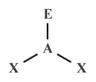 |
120° (117°) | SO2 , O3 |
| AX2 E2 | Bent | 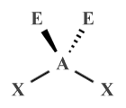 |
109.5° (104.5°) | H2 O, OF2 |
| AX2 E3 | Linear | 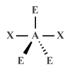 |
180° | XeF2 , XeCl2 |
| AX3 E0 | Trigonal planar |
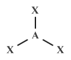 |
120° | BF3 , SO3 |
| AX3 E1 | Trigonal pyramidal |
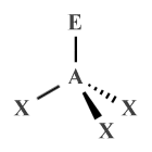 |
109.5° (107°) | NH3 , PCl3 , XeO3 |
| AX3 E2 | T-shaped | 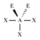 |
90° | ClF3 , BrF3 |
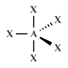
| AX4 E0 | Tetrahedral | 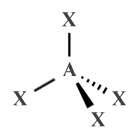 |
109.5° | CH4 , XeO4 |
| AX4 E1 | Seesaw | 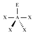 |
120°, 90° (117°, 90°) |
SF4 |
| AX4 E2 | Square planar |
 |
90° | XeF4 |
| AX5 E0 | Trigonal bipyramidal |
 |
90°, 120° | PF5 , PCl5 |
| AX5 E1 | Square pyramidal |
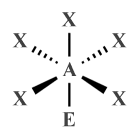 |
90° (87°) | ClF5 , BrF5 , XeOF4 |
| AX5 E2 | Pentagonal planar |
 |
72° | XeF -5 |
| AX6 E0 | Octahedral | 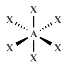 |
90° | SF6 |
| AX6 E1 | Pentagonal pyramidal |
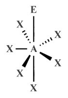 |
90°, 72° | XeOF −5 |
| AX7 E0 | Pentagonal bipyramidal |
 |
90°, 72° | IF7 |
We have already seen some of the molecular geometries represented above as three-dimensional ball-and-stick diagrams. Most of the other geometries are relatively easy to visualise from their description alone. Nevertheless, for the sake of completeness and in order to help you to visualise the shapes of various molecules, The chart below shows the ball-and-stick representations for the shapes we have described.
| AXE Formula(e) | Shape | Ball-and-Stick Diagram |
|---|---|---|
| AX2 E0 , AX2 E3 | Linear | 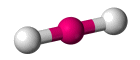 |
| AX2 E1 , AX2 E2 | Bent | 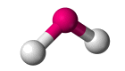 |
| AX3 E0 | Trigonal Planar | 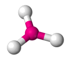 |
| AX3 E1 | Trigonal Pyramidal | 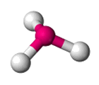 |
| AX3 E2 | T-shaped | 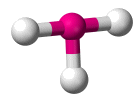 |
| AX4 E0 | Tetrahedral | 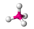 |
| AX4 E4 | Seesaw | 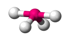 |
| AX4 E2 | Square Planar | 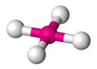 |
| AX5 E0 | Trigonal bipyramidal | 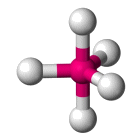 |
| AX5 E1 | Square pyramidal | 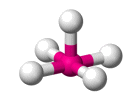 |
| AX5 E2 | Pentagonal Planar | 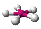 |
| AX6 E0 | Octahedral | 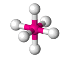 |
| AX6 E1 | Pentagonal Pyramidal | 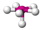 |
| AX7 E0 | Pentagonal bipyramidal | 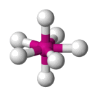 |
VSEPR theory enables us to determine the molecular geometry of a species, providing we know the electronic configuration of that species in terms of the number of bonding domains and lone pairs surrounding the central atom. It works well for nearly all species in which the central atom is a non-metal.
It also works for many species in which the central atom is a metal, although the transition metals are somewhat problematical because non-bonding electron pairs in the valence shell of the d-block elements tend to be stereochemically inactive, which means they do not influence the shape of transition metal complexes in the manner predicted by VSEPR. We'll be looking at the geometry of transition metal complexes in due course.
For most species with a steric number of seven or less we can predict the molecular geometry of the species using the following basic procedure:
| AXE formula(e) | Shape | Bond angle(s) |
|---|---|---|
| AX2 E0 , AX2 E3 | Linear | 180° |
| AX2 E1 | Bent | 120° (117°) |
| AX2 E2 | Bent | 109.5° (104.5°) |
| AX3 E0 | Trigonal planar | 120° |
| AX3 E1 | Trigonal pyramidal | 109.5° (107°) |
| AX3 E2 | T-shaped | 90° |
| AX4 E0 | Tetrahedral | 109.5° |
| AX4 E1 | Seesaw | 120°, 90° (117°, 90°) |
| AX4 E2 | Square Planar | 90° |
| AX5 E0 | Trigonal bipyramidal | 90°, 120° |
| AX5 E1 | Square pyramidal | 90° (87°) |
| AX5 E2 | Pentagonal planar | 72° |
| AX6 E0 | Octahedral | 90° |
| AX6 E1 | Pentagonal pyramidal | 90°, 72° |
| AX7 E0 | Pentagonal bipyramidal | 90°, 72° |
Let's look at some examples. We'll start by looking at the boron trifluoride (BF3 ) molecule. The boron atom, as the least electronegative atom, is the central atom. With only three valence electrons, boron can form single covalent bonds with three fluorine atoms, each of which has seven valence electrons. We end up with a Lewis structure like the one shown below, in which all of the electrons (24 in total) have been accounted for.
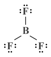
A Lewis structure diagram for the boron trifluoride (BF3 ) molecule
Note that, although the geometry implied in the Lewis structure diagram shown above would be a reasonable assumption based on what we already know about how atoms tend to arrange themselves within molecules, we have not used any formal method to determine the geometry of the BF3 molecule (note also that boron trifluoride is one of the few common molecular substances that is stable despite its central atom not having a complete outer electron shell).
What we can determine from the Lewis structure is that we have three bonding domains and zero lone pairs around the central boron atom, so our AXE formula is AX3 E0 . If we look this formula up in the AXE lookup table (see above), we can see that the BF3 molecule is predicted by VSEPR to have a trigonal planar geometry with bond angles of 120°. Because there are no lone pairs, the electron geometry will be the same as the molecular geometry (trigonal planar).
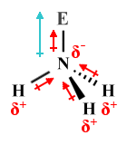
What happens when we introduce one or more lone pairs around the central atom? We'll take a look next at the ammonia (NH3 ) molecule. We can deduce, from its chemical formula, that the ammonia molecule consists of a central nitrogen atom surrounded by three hydrogen atoms (if you have read the article "Lewis Structures" in this section, you may recall that hydrogen can only ever be a terminal atom).
Unlike boron, nitrogen has five valence electrons, so forming single covalent bonds with three hydrogen atoms will give it a complete outer electron shell (nitrogen cannot participate in more than three covalent bonds because it is a period two element - there are no d orbitals to accommodate any additional shared valence electrons). In total, there are eight valence electrons around the central nitrogen atom. Six of these are involved in covalent bonds, leaving the central atom with a single lone pair. Here is the Lewis structure for NH3 :
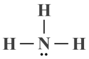
A Lewis structure diagram for the ammonia (NH3 ) molecule
The Lewis structure diagram alone cannot tell us much about ammonia's molecular geometry. If we were to ignore the lone pair, we could assume a trigonal planar geometry similar to that of BF3 , but the lone pair will exert a force of repulsion on each of the bonding domains.
Given that we have three ligands and a single lone pair, we can derive an AXE formula of AX3 E1 . If we look this formula up in the AXE lookup table, we can see that the HN3 molecule is predicted to have a trigonal pyramidal geometry with idealised bond angles of 109.5°, adjusted to 107° because the force of repulsion exerted by the lone pair on each of the bonding domains is greater than the force of repulsion they exert on each other. The presence of the lone pair also means that the electron geometry of NH3 will differ from its molecular geometry (i.e., tetrahedral as opposed to trigonal planar).
We can confidently expect VSEPR to accurately predict the molecular geometry of a great many common polyatomic species, providing there is only one central atom involved (and providing the central atom is a main group element). Things start to get a little more complicated when there is no single central atom, which is the topic we will explore next.
The VSEPR model can be used to predict the structure of species that don't have a single central atom, which is often the case for complex organic molecules (this is also the case, of course, for simple diatomic molecules like O2 , but we don't need VSEPR to predict the geometry of a diatomic species). We'll start, though, by looking at a relatively simple example, namely the acetylene (C2 H2 ) molecule.
Acetylene is a hydrocarbon compound, a highly flammable colourless gas often used for welding due to the high temperature at which it burns when combined with oxygen. As its chemical formula suggests, acatylene consists of two carbon atoms and two hydrogen atoms. Here is the Lewis structure diagram for acetylene:
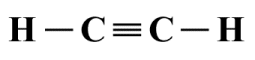
A Lewis structure diagram for the acetylene (C2 H2 ) molecule
Intuitively, from looking at the Lewis structure diagram alone, we would assume a linear geometry for acetylene, which is in fact correct. But how do we apply the VSEPR model to confirm this? In the absence of a central atom, we need to look at each atom that is not a terminal atom - in this case the two carbon atoms - in turn. Each of these atoms will be the central atom of a molecular fragment, and any atoms to directly bonded to them can be treated as ligands.
If we consider the left-hand carbon atom first, then the ligands are the left-hand hydrogen atom and the right-hand carbon atom, which are both covalently bonded to the central carbon atom. Since there are no lone pairs anywhere in the structure, we essentially have a molecular fragment with the AXE formula AX2 E0 , which equates to a linear geometry.
There is no real need to repeat the exercise for the right-hand carbon atom, because the molecular fragment built on it will be a mirror image of that built on the left-hand carbon atom. Since the C≡C bond is common to both fragments, we can conclude that the overall geometry of the C2 H2 molecule is indeed linear.
Let's apply the same technique to a somewhat more complex hydrocarbon compound, ethane (C2 H6 ) - an important constituent of natural gas. The ethane also has a central structure consisting of two covalently bonded carbon atoms. This time, however, each carbon atom is covalently bonded to three hydrogen atoms. Here is the Lewis structure diagram:
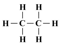
A Lewis structure diagram for the ethane (C2 H6 ) molecule
It's not obvious from looking at the Lewis structure diagram what the overall molecular geometry should be. If we again consider the left-hand carbon atom to be the central atom of a molecular fragment, we can see that it is covalently bonded to four ligands - three hydrogen atoms and a single carbon atom. Once again, there are no lone pairs involved, so the AXE formula for this fragment is AX4 E0 , which indicates a tetrahedral geometry, with bond angles of 109.5°.
Since the right-hand fragment will again be a mirror image of the left-hand fragment, and the C-C bond is common to both fragments, the overall geometry of the ethane molecule is predicted by VSEPR to consists of conjoined tetrahedra, as illustrated below.
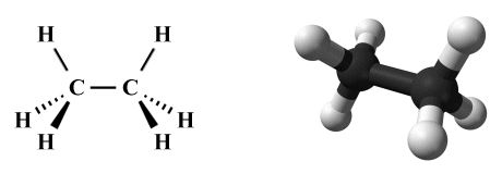
The perspective diagram and ball-and-stick model for ethane (C2 H6 )
In order to show that VSEPR can also be applied to complex molecules that are not symmetric, we'll look at one more example, the organic compound methyl isocyanate or isocyanatomethane (C2 H3 NO) - a colourless, toxic and highly flammable liquid that is used in the production of pesticides, polyurethane foam and plastics. Here is the Lewis structure diagram for C2 H3 NO:
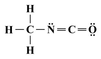
A Lewis structure diagram for the methyl isocyanate (C2 H3 NO) molecule
Once again, we have carbon and hydrogen atoms, but we now also have a nitrogen atom and an oxygen atom to consider. The hydrogen atoms and the oxygen atom can clearly be considered terminal atoms, so we effectively have three molecular fragments to deal with.
The first fragment is based on the left-hand carbon atom. It has four ligands and no lone pairs, giving the AXE formula AX4 E0 - a tetrahedral geometry with bond angles of 109.5°. The second fragment, based on the nitrogen atom, has just two ligands, but this time the central atom has a lone pair. The resulting AXE formula of AX2 E1 gives this fragment a bent geometry, with a nominal bond angle of 120°.
The final fragment has the second carbon atom as its central atom, again with two ligands. This time, however, in the absence of any lone pairs, the AXE formula of AX2 E0 gives us a linear geometry with a bond angle of 180°. If we tie the three fragments together, remembering that each pair of fragments shares a covalent bond, then VSEPR predicts the following overall shape for the molecule:
The perspective diagram and ball-and-stick model for methyl isocyanate (C2 H3 NO)
We have stated elsewhere that the predominant factors that determine the dipole moment of a polyatomic species are geometry, overall charge, and the relative electronegativities of its constituent atoms. If a species has no overall dipole moment, it will be non-polar. Otherwise, it will be polar to some degree. The degree of polarity will be dependent on the strength of the partial charges within the molecule and the distances between them.
VSEPR can help us to predict the overall geometry of a polyatomic species from which, together with other factors, we can usually determine whether or not that species will have a dipole moment. We have already seen examples of polyatomic molecules with polar covalent bonds in which the overall polarity of the molecule is determined by its geometry.
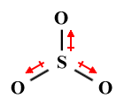
For example, the CO2 molecule has two identical polar covalent bonds, each with the same dipole moment, but because of its linear geometry these equal dipole moments act in opposite directions and cancel each other out, leaving the CO2 molecule with a net dipole moment of zero. The H2 O molecule, on the other hand, has a non-zero net dipole moment (1.8546 debyes, for the interested reader) because, despite having two identical covalent bonds, It has a bent geometry in which the individual bond dipoles are oriented at 104.5° to each other and thus do not cancel each other out.
Keep in mind that dipole moments are vector quantities - they have both magnitude and direction. Thus, whereas each bond within a polyatomic species has its own dipole moment, the overall dipole moment of the species is the vector sum of these dipole moments. Species in which that vector sum is zero are non-polar. Species in which the vector sum is non-zero are polar to a degree that is dependent on the magnitude of the vector sum.
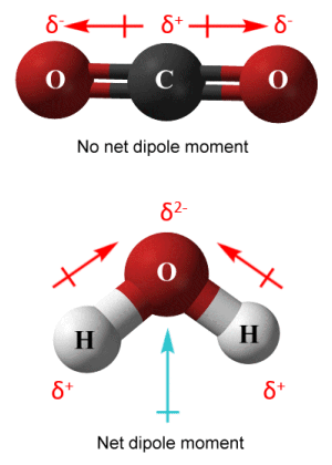
Dipole moments in CO2 (top) and H2 O (bottom)
In order to avoid any possible confusion, we should point out that we have adopted the convention used in chemistry in the diagram above in the sense that the arrows representing dipole moment point from positive to negative, both for individual bonds and for the molecule as a whole. Physicists tend to use the opposite convention (arrows point from negative to positive).
As a general rule of thumb, non-polar species are symmetric and polar species are asymmetric - but how do we determine which of these categories a species falls into? One approach is to start by assuming that a species is symmetric, and then either prove or disprove that assumption by applying some simple rules.
The first rule is that if the central atom has one or more lone pairs, the species is probably asymmetric. We say probably, because as we shall see there are exceptions to this rule. The second rule is that if the ligands (terminal atoms) are not all of the same element, the species is asymmetric. This rule applies regardless of whether or not the central atom has one or more lone pairs.
The simplest case to consider is the diatomic molecule. If the molecule is homonuclear (both atoms are of the same element, as is the case for O2 ), the molecule is symmetric. Furthermore, because both atoms are the same, and therefore have the same electronegativity, the covalent bond they share is non-polar. The O2 molecule thus has no overall dipole moment, and is non-polar.
If the diatomic molecule is heteronuclear (the atoms are of different elements, as they are in CO), the molecule is asymmetric. The bond between the atoms in CO will be polar because oxygen is more electronegative than carbon, so the shared electrons spend more time around the oxygen atom. Thus, despite having a linear geometry, the CO molecule has an overall dipole moment due to the unequal distribution of charge density, and is polar.
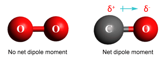
Charge density distribution in molecular oxygen (O2 ) and carbon monoxide (CO)
Symmetry is a pre-requisite for non-polar molecules. The chart below provides examples of non-polar polyatomic species and the shapes they adopt. Note that all of the ligands are of the same element, so individual bond dipole moments will cancel each other out and the species will have no net dipole moment. Note also that some of these species are considered to be symmetric despite the presence of lone pairs around the central atom (these are the exceptions to the lone pair rule we mentioned earlier; their dipole moment contributions are not shown, since they cancel each other out).
| Species | Shape | Perspective Diagram | Bond Angle(s) | AXE formula |
|---|---|---|---|---|
| CO2 | Linear | 180° | AX2 E0 | |
| XeCl2 | Linear | 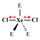 |
180° | AX2 E3 |
| SO3 | Trigonal planar |
 |
120° | AX3 E0 |
| CH4 | Tetrahedral | 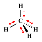 |
109.5° | AX4 E0 |
| XeF4 | Square planar |
 |
90° | AX4 E2 |
| PCl5 | Trigonal bipyramidal |
 |
90°, 120° | AX5 E0 |
| XeF -5 | Pentagonal planar |
 |
72° | AX5 E2 |
| SF6 | Octahedral |  |
90° | AX6 E0 |
| IF7 | Pentagonal bipyramidal |
 |
90°, 72° | AX7 E0 |
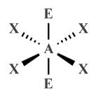
In the linear XeCl2 molecule, for example, three lone pairs are spaced equidistantly around the central atom in equatorial positions. The molecule is considered to be symmetric because the lone pairs exert the same force of repulsion on each of the two chlorine atoms, which occupy axial positions.
In the square planar XeF4 molecule, it is the four fluorine atoms that occupy equidistant equatorial positions around the central atom, with two lone pairs in axial positions exerting equal and opposite forces of repulsion from above and below. A similar arrangement is found in the pentagonal planar XeF -5 polyatomic ion, except that in this case there are five fluorine atoms in equatorial positions around the central atom.
There are of course many instances of species that appear to be symmetric but are in fact asymmetric and are therefore polar. A case in point is the trichloromethane (CHCl3 ) molecule. Trichloromethane, also known as or chloroform, is an organic liquid which was often used in the past as an anaesthetic. It has a symmetric (tetrahedral) molecular geometry, but the atoms bonded to the central carbon atom (three chlorine atoms and one hydrogen atom) are not identical.
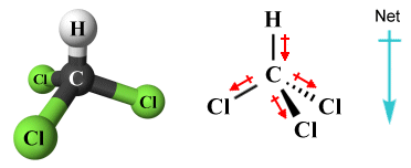
The trichloromethane (CHCl3 ) molecule is polar
Even if a species has ligands that are all of the same type, it may still be asymmetric due to the presence of one or more lone pairs around the central atom. These lone pairs distort the molecular geometry and change the bond angles within the molecule. As a result, individual bond dipole moments cannot cancel each other out and the species has an overall dipole moment. The chart below provides examples of polyatomic species that have ligands of only one element but that are nevertheless polar due to the presence of lone pairs.
| Species | Shape | Perspective diagram | Bond Angle(s) | AXE formula |
|---|---|---|---|---|
| SO2 | Bent | 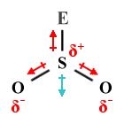 |
120° (117°) | AX2 E1 |
| H2 O | Bent | 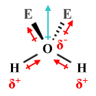 |
109.5° (104.5°) | AX2 E2 |
| NH3 | Trigonal pyramidal |
 |
109.5° (107°) | AX3 E1 |
| BrF3 | T-shaped |  |
90° | AX3 E2 |
| SF4 | Seesaw | 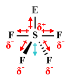 |
120°, 90° (117°, 90°) |
AX4 E1 |
| BrF5 | Square pyramidal |
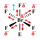 |
90° (87°) | AX5 E1 |
Determining the polarity of complex molecules that have an irregular geometry is generally more difficult, and we need to determine whether these molecules are polar or non-polar on a case-by-case basis remembering that, as we mentioned earlier, the overall dipole moment of a species is the vector sum of a number of individual dipole moments.
Many complex organic molecules are considered to be non-polar because they consist of long hydrocarbon chains in which the C-C bonds are completely non-polar and the dipole moments found in the C-H bonds are too weak to give the molecule as a whole a significant dipole moment. Also, because there tend to be a significant number of C-H bonds, all pointing in different directions, their dipoles tend to cancel each other out. However, the presence of a strongly polar bond within the structure could upset this balance and give the molecule a significant overall dipole moment.
The principles of VSEPR are relatively easy to apply and enable us to accurately predict the shape of a large number of polyatomic species. It does have a number of limitations, however, and does not work for all species. Even when it does accurately predict the shape of a molecule or polyatomic ion, it can often only give us an approximation when it comes to bond angles, and the measured values do not always match the idealised values predicted by VSEPR. It also tells us nothing about bond length, which means that we cannot accurately calculate the dipole moment of a species, although we can usually determine its overall polarity or lack thereof.
The relatively simplistic nature of the VSEPR model is what makes it easy to use, but it also ignores many factors that can be influential in determining molecular geometry. It assumes, for example, that bonding domains remain localized between atoms, whereas both valence bond theory and molecular orbital theory acknowledge the role played by delocalised electrons. It does not differentiate between different covalent bond orders, or consider the nature of orbital interactions. Nor does it take the atomic mass of ligands into account.
Thus, although VSEPR is highly successful in predicting the molecular geometry of many chemical substances, it does not always produce accurate or meaningful results. For example, VSEPR predicts a bent structure similar to that of H2 O for lithium oxide (Li2 O), and a linear structure similar to that of BeCl2 for magnesium chloride (MgCl2). However, the bonds in crystalline solids such as MgCl2 and Li2 O are ionic rather than covalent, resulting in formula units that participate in a crystal lattice structure rather than forming discrete molecules. VSEPR is thus not really applicable to these substances.
VSEPR also fails to correctly predict the structure of some molecular substances in which unpaired electrons are found. Consider the methyl radical (CH•3 or [CH3 ]•), an organic compound that commonly occurs as an intermediate product in petroleum cracking (part of the petroleum refining process). The central carbon atom in CH•3 is covalently bonded to three hydrogen atoms, which leaves it with an unpaired electron. The VSEPR model treats the unpaired electron as if it were a lone pair, giving an AXE formula for CH•3 of AX3 E1 , which would indicate a trigonal pyramidal molecular geometry.
The reality is that CH•3 has a trigonal planar geometry, because the force of repulsion exerted by the lone electron on the C-H bonds is not sufficient to distort the molecule into a pyramidal geometry, although very little additional energy would be required to do so. Substiting more electronegative atoms for the hydrogen atoms does in fact produce radicals with a pyramidal geometry, as is the case with the trifluoromethyl radical (CF•3 ).
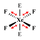
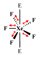
Even lone pairs do not always have the influence over molecular geometry predicted by VSEPR. A case in point is the xenon hexafluoride (XeFl6 ) molecule, which has a total of fifty valence electrons. If we draw the Lewis structure diagram for XeFl6 , we will see that twelve valence electrons are accounted for by the six sigma bonds formed between xenon and the fluorine atoms. Of the remaining thirty-eight valence electrons, thirty-six are taken up by lone pairs around the six fluorine atoms, leaving a single lone pair on the central atom. Here are the Lewis structure diagram, and the perspective diagram predicted by VSEPR, for XeF6 :
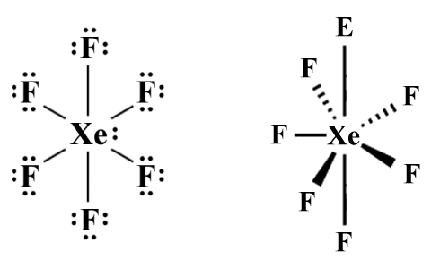
The Lewis structure diagram and perspective diagram for XeF6
The AXE formula for XeF6 according to VSEPR is AX6 E1 , which predicts a pentagonal pyramidal molecular geometry. Because of something called the hybridization of orbitals - a complete explanation of which is beyond the scope of this article (but we'll be looking at it elsewhere) - the molecule actually adopts a distorted octahedral shape rather than the pentagonal pyramidal shape predicted by VSEPR. For now, we will simply explain the discrepancy between what VSEPR predicts and what actually happens by saying that, following hybridisation, the electrons in the lone pair get split up and are promoted into vacant 5d orbitals, minimising their influence on molecular geometry.
Another area in which VSEPR can lead to an incorrect conclusion concerns isoelectronic species. In the context of this article, we use the term isoelectronic to refer to two or more molecules or polyatomic ions that have the same number of valence electrons and the same electronic structure. The central atom will be surrounded by the same number of bonding domains and lone pairs. Only the atoms involved will be different.
The chemical characteristics of isoelectronic species are often the same, although this is not guaranteed to be the case. But what about their molecular geometry? VSEPR predicts the shape of a species based on the number of bonding domains and lone pairs surrounding a central atom. It will therefore predict the same shape for all species belonging to a particular isoelectronic series. However, research has shown that isoelectronic species do not always have the same geometry.
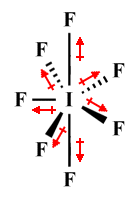
To illustrate, let's consider the interhalogen compound iodine heptafluoride or iodine(VII) fluoride as it is sometimes known, which has the chemical formula IF7 . VSEPR correctly predicts that an IF7 molecule will have a pentagonal bipyramidal structure because it has seven bonding domains and zero lone pairs, giving it the AXE formula AX7 E0 . The polyatomic ion heptafluorotellurate(1-), which has the chemical formula [TeF7 ] -, also has a central atom surrounded by seven covalently bonded fluorine atoms and no lone pairs. Here are their respective Lewis structure diagrams:
![Lewis structure diagrams for IF7 and [TeF7]-](images/matter_0127.gif)
Lewis structure diagrams for IF7 and [TeF7 ] -
As you can see, both species have the same number of valence electrons and bonding domains around the central atom, and both have zero lone pairs around the central atom, which makes them part of the same isoelectronic group. Consequently, VSEPR predicts exactly the same molecular geometry for [TeF7 ] - (pentagonal bipyramidal) as it does for IF7 . However, and x-ray diffraction studies have shown that the equatorial fluorine atoms of [TeF7 ] - are not coplanar, and that the bond lengths between the central atom and the equatorial fluorine atoms in each case is different. VSEPR thus fails to correctly predict the shape of the [TeF7 ] - molecule.
Transition metal complexes (also known as coordination complexes) are molecules that contain groups of atoms arranged around a central transition metal ion. We have already mentioned that non-bonding electron pairs in the outer shells of transition metal atoms tend to be stereochemically inactive, which means they do not have an influence on molecular geometry.
When dealing with transition metal complexes, we can substitute VSEPR with something called the Kepert model, named after David L. Kepert who developed it. This model works along similar lines to VSEPR except that it ignores all non-bonding electrons on transition metal atoms. The formula used to determine molecular geometry is thus effectively the VSEPR formula AXn , except that it is more often expressed as MLn , where M stands for metal, L stands for ligand, and the subscript n represents the coordination number.
The coordination number, in the current context, is the number of atoms, ions or molecules bound to a central atom or ion in a transition metal complex (collectively referred to as ligands), and typically ranges from two up to nine, although higher numbers may be encountered occasionally. For the purpose of this discussion, we will only consider complexes with a coordination number of six or lower. The table below shows the molecular geometry predicted by the Kepert model for transition metal complexes with coordination numbers of two through six.
| Formula | Shape | Example |
|---|---|---|
| ML2 | Linear | HgCl2 |
| ML3 | Trigonal planar | - |
| ML4 | Tetrahedral | NiCl 2−4 |
| Square planar | - | |
| ML5 | Trigonal bipyramidal | Fe(CO)5 |
| Square pyramidal | MnCl5 2− | |
| ML6 | Octahedral | WCl6 |
As you can see, the geometry predicted for a transition metal complex by the Kepert model depends mainly on its coordination number. In the case of both ML4 and ML5 , however, more than one variant may occur (this is also the case for complexes with a coordination number higher than six). The geometry adopted in such cases depends on three major factors - the nature of the transition metal atom at the centre of the complex, the nature of the ligands, and the coordination number.
Ultimately, the geometry of transition metal complexes is governed by the way in which transition metals interact with ligands. There is a clear correlation between the coordination number (i.e., the number of ligands) and the molecular geometry. Since the most commonly occurring coordination numbers are 4, 5 and 6, the most common geometries are tetrahedral (or sometimes square planar), trigonal bipyramidal (sometimes square pyramidal), and octahedral.
The metal-ligand bonds in transition metal complexes will usually be as far away from each other as possible due to the force of repulsion exerted by the electron pairs in the bonds on one another. Complexes with four ligands thus tend to have a tetrahedral molecular geometry, with a bond angle of 109.5°. In some cases, however - notably in complexes in which the central metal atom has eight electrons in d orbitals - the interaction between the ligands and the d orbitals offsets this tendency and the complex instead adopts a square planar geometry.
Complexes with five ligands tend to have a trigonal bipyramidal geometry because this configuration allows the five ligands achieve the maximum separation, but a square pyramidal structure can also occur, again depending on the interaction between the ligands and the d orbitals.
An in-depth examination of the geometry of transition metal complexes would require diving quite deeply into the electronic configuration of transition metals, and taking a detailed look at how bonds are formed between transition metals and ligands in transition metal complexes. Such an in-depth examination is beyond the scope of this article, but we hope to explore the subject more fully in a future article.