| Author: | |
| Website: | |
| Page title: | |
| URL: | |
| Published: | |
| Last revised: | |
| Accessed: |
Requirements analysis is carried out in two stages. First of all, an investigation of the current system is carried out. This enables the scope of the project to be determined, and highlights any problems with the system. The kind of problems identified could include redundant processing or processes that create bottlenecks, superfluous procedures, or excessive data redundancy. The initial investigation should identify users (and potential users) of the system, define the nature, volume and frequency of business transactions handled, and catalogue any existing hardware or software used.
The second stage is to investigate a number of possible business options, including the identification of any additional features or services that the new system may be required to provide. The existing and proposed systems can be modelled using physical and logical Data Flow Diagrams (DFDs). A physical DFD shows how the system is (or will be) constructed, whereas a logical DFD is not concerned with the physical aspects of the system.
Physical DFDs clarify which processes are manual and which are automated, and describe processes in more detail than logical DFDs. They also show the sequence in which processes must be carried out, identify temporary data stores, specify the actual names of files and printouts, and define any controls used to ensure that processes are carried out correctly.
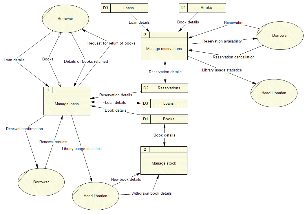
Logical DFDs concentrate on the logical flow of data between business processes rather than the physical implementation of the system, and allow analysts to understand the business more clearly. They attempt to rationalise the lowest-level processes and group them together to form the Level 1 DFD. They also attempt to rationalise the data stores in the system, to relate each data store to one or more entity in the Logical Data Structure (LDS), and ensure that each entity is found in only one data store. The logical DFD provides a solid basis on which to carry out a discussion of the system with users, and results in more stable systems. It also facilitates the elimination of redundancy, and makes it easier to create the final physical model.

A Level 1 DFD for a simple library system
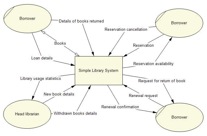
DFDs at different levels are part of a structured hierarchy, with the lowest tier showing the greatest level of detail. Functional decomposition is carried out until an appropriate level of detail has been attained, and a definitive Elementary Process Description (EPD) is defined for each lowest level process. DFDs are used to analyse the system to ensure that the final design is complete, and to provide important system documentation. The highest level of DFD is the context diagram, which shows the system's relationship to the external entities with which it interacts.

A context diagram for a simple library system
Common Errors in DFDs include the omission of data flows, showing data flowing in the wrong direction, connecting data stores and external entities directly to each other, and incorrectly labeling processes or data flows. It is recommended not to include more than nine processes on a DFD. A lower-level (child) DFD should have the same data flows in and out as its parent process.
The specific additions and changes to the existing system that will be incorporated into the new system can be modeled using a revised set of DFDs. These additions and changes should be recorded in a document called the requirements catalogue. The requirements for the new system can be further categorised into those that are mandatory ("must have" features), and those that are seen as desirable but not essential ("would like to have" features).
The data used in the current system is also examined and defined in a process that attempts to model the structure of the data by grouping data items into logical data entities. The process ignores the method of data storage used, or the physical location of the various data stores, and concentrates instead on the logical structure of the system's data. The relationships between the various data entities are defined, together with the key data values that are used to link them together. Data modelling can also be used to identify any shortcomings or omissions in the current system's dataset that should be addressed by the new system, and any new requirements identified are added to the requirements catalogue. Data modelling techniques will be looked at in more detail elsewhere.
The outcome of the requirements analysis stage is a detailed requirements specification that contains sufficient information to allow the new information system to be designed. A clear boundary will be defined for the proposed system that specifies what processes are included within it, and the external entities with which it interacts. The required system inputs and outputs are specified, together with the functionality that the system must provide. Performance requirements will be outlined in terms of user response times, processing speed, the volume of data storage to be provided, and the number and frequency of transactions to be handled. Special requirements should also be identified, such as the level of security to be implemented and the facilities that should be provided to enable routine maintenance and the backup of system data to be carried out efficiently. The specification may also make specific recommendations in terms of the application software that must be enabled to run on the system, and the minimum specification for system hardware such as file servers, workstations, communications devices, and network cabling.