Frame Relay
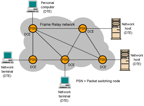
Frame relay is a fast, connection-oriented, packet-switching technology (based on the older X.25 packet switching technology) originally intended for use in ISDN networks, but now widely used in a variety of local and wide area networks. It can be used, for example, to interconnect local area networks. Unlike X.25, frame relay is purely a data-link layer protocol, and does not provide error handling or flow control. When an error is detected in a frame, it is dropped. Upper layer protocols are responsible for detecting and retransmitting dropped frames. The devices attached to a frame relay network are either DTEs (data terminating equipment), typically located on customer premises (for example, computer terminals, routers, and bridges), and DCEs (data circuit-terminating equipment), which are carrier-owned internetworking devices that provide network switching services (usually packet switches). The diagram below shows the relationship between these devices.

Relationship between DTEs and DCEs in a frame relay WAN
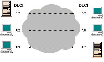
A virtual circuit (which can be either switched or permanent) must be established between two end points before data can be transferred. Each virtual circuit is uniquely identified by a data-link connection identifier (DLCI), typically assigned by the frame relay service provider. A number of virtual circuits can be multiplexed onto a single physical circuit, and a single virtual circuit can pass through any number of packet switching nodes. For switched circuits, there will be the additional overhead of call setup and termination. Establishing, maintaining and terminating a switched virtual circuit involves the same signaling protocols as are used in ISDN. Permanent virtual circuits may be established for frequent data transfers, and do not require call setup and termination. Frame relay DLCIs have local significance, which means that their values are unique in a LAN, but not necessarily in a frame relay WAN. The diagram below illustrates how two different DTE devices can be assigned the same DLCI value within one frame relay WAN.

Virtual circuit identifiers
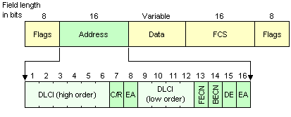
Frame relay implements simple congestion-control mechanisms, each of which uses a single bit subfield within the Address field of the frame relay frame. If the network is congested, packet switching nodes will set the forward-explicit congestion notification (FECN) bit to 1 in each frame received. The destination DTE device passes this information to a higher-layer protocol, which may either initiate flow control or ignore it. Packet switching nodes will set the backward-explicit congestion notification (BECN) bit to 1 in frames travelling in the reverse path of frames with their FECN bit set, to inform the receiving DTE device that a particular path through the network is congested. Again, the DTE device passes this information to a higher-layer protocol, which may either initiate flow control or ignore it. The discard eligibility (DE) bit can be set to 1 to identify low-priority traffic that can be dropped during periods of network congestion.
Frame relay frame format

The standard frame relay frame format
The fields of the standard frame relay frame are described below.
- Flags - a bit pattern that delimits the beginning and end of the frame (01111110)
- Address - contains the following subfields:
- Data-link connection identifier (DLCI) - a 10-bit field that identifies a virtual connection
- Extended address (EA) - if set to 1, the current byte is the last in the DLCI (current implementations use a two-byte DLCI)
- Command/response (C/R) - not currently defined
- Congestion control - a 3-bit field that contains the FECN, BECN and DE bits
- Data - up to 16,000 bytes of user data
- Frame check sequence (FCS) - used for error detection
The local management interface (LMI)
The frame relay local management Interface (LMI) extends the basic frame relay specification to provide a number of features for managing complex internetworks. The global addressing extension makes it possible for DLCI values to have global significance, making them unique within the frame relay WAN, allowing individual network interfaces (and the end user devices attached to them) to be identified using standard address-resolution and discovery techniques. LMI virtual circuit status messages provide communication and synchronisation between DTE and DCE devices, and are used to report on the status of permanent virtual circuits. The LMI multicasting extension saves bandwidth by allowing routing updates and address-resolution messages to be sent to specific multicast groups of routers only.

The LMI frame format
The LMI frame fields are described below.
- Flag - delimits the beginning and end of the frame
- LMI DLCI - identifies the frame as an LMI frame instead of a basic frame relay frame
- Unnumbered information indicator - sets the poll/final bit to zero
- Protocol discriminator - always contains a value indicating that the frame is an LMI frame
- Call reference - always contains zeros (this field is not currently used)
- Message type - either status-enquiry (used to enquire about the status of a permanent virtual circuit) or status (used to respond to status-inquiry messages, and as keepalives)
- Information elements - contains a variable number of information elements (IEs), each comprising an IE Identifier that uniquely identifies the IE, and an IE Length that indicates the length of the IE
- Data - one or more bytes of user data
- Frame check sequence (FCS) - used for error detection
