| Author: | |
| Website: | |
| Page title: | |
| URL: | |
| Published: | |
| Last revised: | |
| Accessed: |
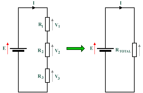
In the left-hand figure in the diagram below, three resistors are connected in series with a battery, E. The total resistance of the circuit is obtained simply by adding the three resistances together. In the right-hand figure, a single resistor with a value of RTOTAL is used to provide the same load resistance as the three resistors on the left-hand side. The value of RTOTAL is thus equivalent to R1 + R2 + R3. The current flowing through the two circuits is exactly the same, and the voltage drop across RTOTAL is equal to the sum of the voltage drops across R1 + R2 + R3 (and is also equal in magnitude to the supply voltage produced by E).

These circuits are equivalent in terms of total resistance and current
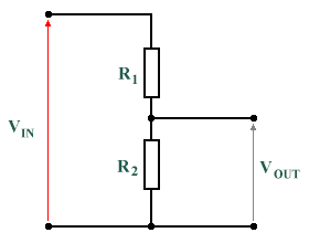
Sometimes it is useful to be able to divide the potential of a circuit so that an output voltage that is a known fraction of the input voltage (known as a reference voltage) can be obtained. A simple example of a potential divider consists of two resistors in series, as shown in the diagram below. The input voltage is applied across resistors R1 and R2 which are connected in series. The output voltage is the voltage across R2.

A typical potential divider consisting of two resistors in series
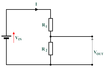
The circuit divides the supply voltage into two separate voltage drops in the same ratio as the two resistor values. Using Ohm's Law, we can express the output voltage using the following equation:
| VOUT = VIN × | R2 |
| R1 + R2 |
A potential divider is most often used to produce a reference voltage that is both precise and stable. Little or no current should be drawn by the attached load, which must therefore have a very high resistance. Using a potential divider as a voltage source is not usually practical. Consider what would happen if we placed a load in parallel with R2, for example. The load itself will have a resistance, which will act in parallel with the resistance provided by R2. Since the combined resistance of two or more resistors in parallel is always less than the resistance of the smallest of the resistors, and because the combined resistance will now be acting in series with R1 in the circuit, the overall circuit resistance will be reduced. This will increase the total current passing through the circuit (remember Ohm's law). This increased current will pass through R1 increasing the voltage drop across it and reducing VOUT (since the two voltage values must always sum to VIN).
For the potential divider circuit shown above, the application of the circuit divider as a voltage source is only practical if the load resistance is considerably larger than R2 although it is not a particularly power-efficient solution, since a significant amount of power will be dissipated in the potential divider in the form of heat. We will be looking at the relationship between voltage, current and power in another section.

A potential divider consisting of two resistors in series with a supply voltage