| Author: | |
| Website: | |
| Page title: | |
| URL: | |
| Published: | |
| Last revised: | |
| Accessed: |
Like most of the quantities we talk about in this section, electric current is one of the base quantities defined by the International System of Units. The internationally agreed base unit for electrical current is the ampere. Frequently-used sub-multiples of the ampere include the milliampere - one milliampere is equal to one thousandth of an ampere - and the microampere - one microampere is equal to one millionth of an ampere. Electric current is the flow of electric charge. Before we can talk about electric current, therefore, we should at least attempt to define electric charge.
The symbol for charge is the italicised upper-case letter Q. Defining charge is far from easy. According to Wikipedia, for example: "Electric charge is the physical property of matter that causes it to experience a force when placed in an electromagnetic field." However, here is what Wikipedia has to say about electromagnetic fields: "An electromagnetic field . . . is a physical field produced by electrically charged objects".
Search where you will for enlightenment, you will not find a completely satisfactory definition for electric charge. Some sources will state that it is a "fundamental property of elementary particles of matter". This is at best an ambiguous statement, but let's assume that we are talking about the subatomic particles from which atoms are primarily constructed - the protons and neutrons that make up the nucleus of the atom, and the electrons that surround it.
Of these three different kinds of subatomic particle, only the proton and electron carry a charge. The neutron is electrically neutral (the clue is in the name). What we can say is that the charge carried by an electron is equal in magnitude to the charge carried by a proton. The difference is that, whereas the charge carried by the proton is positive, the charge carried by the electron is negative.
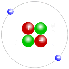
Protons and electrons carry equal but opposite charge
Actually, the distinction between positive and negative is somewhat arbitrary. The important thing to note is that the charge carried by an electron has the opposite polarity to that carried by a proton. Equally important is the fact that charge is responsible for the electrostatic forces of repulsion and attraction that exist between elementary particles. Like charges repel each other; unlike charges attract one another.
The force acting between two charged particles is called the coulomb force, after the French military engineer and physicist Charles-Augustin de Coulomb (1736-1806). Coulomb developed a law (known as Coulomb's law) that describes the electrostatic forces of attraction and repulsion between two charged particles (the unit of charge is the coulomb (symbol: C), also named after him). The law states:
"The magnitude of the electrostatic force of attraction or repulsion between two point charges is directly proportional to the product of the magnitudes of charges and inversely proportional to the square of the distance between them"
Electrons that spend most of their time relatively close to the nucleus of an atom will be strongly attracted by the positively charged protons in the nucleus Those further away from the nucleus will not feel such a strong attraction. As a result, electrons in an atom's outer shell are sometimes able to break free of the atom altogether.
The elementary charge on a single proton is designated as e. The elementary charge on an electron is designated as -e. One coulomb of charge is the amount of (positive) charge carried by approximately 6.242 × 10 18 protons. Conversely, minus one coulomb of charge is the amount of (negative) charge carried by approximately 6.242 × 10 18 electrons.
We stated above that electric current is the flow of electric charge. We know that electric charge is an intrinsic property of certain fundamental particles - namely the electron, which carries a single unit of negative charge, and the proton which carries a single unit of positive charge. Therefore, in order for a current to exist, there must be a flow of charged particles between two points.
A charged particle that participates in a current flow is called a charge carrier. Charge carriers are usually electrons, but they can also be ions (an ion is an atom that has an overall positive or negative charge due to having lost or gained one or more electrons). Ions tend to be the charge carriers in electrolytic solutions, for example. In a salt water solution, sodium chloride (salt) dissociates to form positive sodium ions and negative chloride ions.
In semiconductor materials, the charge carries can be either electrons or "holes". A hole, in this context, is essentially the absence of an electron in a p-type semiconductor material (the "p" indicates that the materials has a positive bias) as opposed to an n-type semiconductor material ("n" indicates a negative bias). The p- and n-type semiconductor materials are created by doping - essentially, adding small amounts of chemical substances (called impurities) to a semiconducting element like silicon or germanium.
In most of the situations we are interested in, the charge carriers will be electrons. Unless otherwise stated, the term "electric current" (or just "current") will henceforth refer to the movement of electrons between two points.
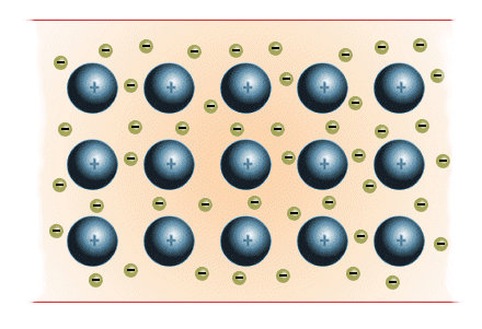
Free electrons in a copper wire act as charge carriers
Current is the movement of electrical charge past a point, in a given direction. The unit of current is the ampere (symbol: A) often shortened to amp. It takes its name from the French physicist and mathematician André-Marie Ampère (1775-1836), considered by many to be the father of classical electrodynamics - the branch of theoretical physics concerned with the interactions between electric charge and current. The symbol for current is the italicised upper-case letter I, used by Ampère and thought to originate from the French phrase intensité de courant (which translates to current intensity).
We have established that electric current is the flow of electric charge past a point in a particular direction. One ampere is defined as one coulomb of charge passing a given point in a circuit in one second. In other words - assuming that the charge carriers are electrons - a current of one ampere requires approximately 6.242 × 10 18 electrons to move past a point in a circuit during a one-second time frame. The Internation System of units gives a precise definition of current based on a fixed value for the the elementary charge e of 1.602 176 634 × 10–19 coulombs:
"The electric current corresponding to the flow of 1/(1.602 176 634 × 10−19) elementary charges per second"
Current is thus the movement of electrons through a circuit, and the amount of current flowing in the circuit will depend on the number of electrons moving past a given point in a circuit per unit time. The greater the number of electrons, the higher the current. The current I flowing in a circuit can be expressed algebraically as follows:
| I = | Q |
| t |
where:
Q is the amount of charge in coulombs
t is the time in seconds
An analogy often used for current flow in an electrical circuit is that of water flowing through a pipe. The number of electrons flowing past a point in the circuit in a given amount of time is analogous to the number of water molecules passing a point in the hose during the same time frame.
Water flows through the pipe in a particular direction because the water pressure at one end of the pipe is greater than the water pressure at the other end of the pipe, but at the same time the flow of water is constrained by the pipe's diameter. It is easier for water to flow through a large diameter pipe than through a small diameter pipe.
The water pressure pushing the water through a pipe is analogous to the potential difference, or voltage, responsible for pushing the electrons through an electrical circuit. The degree to which the flow of water through a pipe is constrained by the diameter of the pipe is analogous to the amount of resistance to the flow of electrons encountered in an electrical circuit (we will have more to say about voltage and resistance shortly).
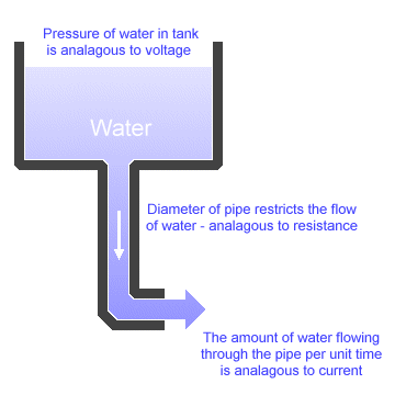
The flow of water in a pipe is a good analogy for the flow of current
We can think of the water in the tank as the charge held by a battery. At first, the water pressure - which represents voltage - is high because the tank is full. As the tank empties the water pressure drops (water pressure falls as the depth of the water decreases), and the flow of water through the pipe - which represents current - will slow. The diameter of the pipe represents resistance, because it limits the rate at which water can flow through the pipe at a given pressure.
Assuming the diameter of the pipe (i.e. the "resistance") remains constant, the volume of water flowing through the pipe per unit time (i.e. the "current") will depend on the depth of the water in the tank (the "voltage"). Keeping the tank topped up is the equivalent of supplying a steady voltage to the circuit.
The voltage supplied by a flashlight battery is created by a chemical reaction that occurs within the battery each time the circuit is closed (i.e. when the flashlight is turned on). The chemical reaction keeps the voltage at a certain level - the equivalent of "topping up the tank" - throughout the operational lifetime of the battery.
When there is no current flowing in an electrical circuit, the free electrons in the circuit will move in random directions within the conducting wires and other components that make up the circuit. There will be no overall movement of electrons in any particular direction. The electrons will only start to move in the same direction - creating a measurable flow of current - when acted on by an external force.
The external force in question takes the form of a potential difference being applied across the circuit. This potential difference is provided by a voltage source - a battery for example - that creates a region of negative charge at one end of the circuit, and a region of positive charge at the other end of the circuit. The voltage source achieves this internally by driving electrons away from its positive terminal and towards its negative terminal.
Once the circuit is closed, the difference in potential placed across the circuit between the positive and negative terminals of the voltage source creates an electric field. Under the influence of the electric field, the free electrons in the circuit all begin moving in the same direction - away from the negatively charged terminal and towards the positively charged terminal.
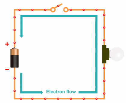
Free electrons move when a voltage is applied
It is a common misconception to imagine that electrons flow through a circuit at high speed. In fact, the passage of electrons through a circuit is so slow that we talk about them "drifting". Despite the fact that they are now all moving in the same overall direction, the electrons still follow a relatively haphazard course through the conducting wires of the circuit, and frequently collide with atoms.
The movement of electrons through a circuit can probably best be described as a migration, and the average rate at which electrons move towards the positive terminal is referred to as the drift speed. Although there are various factors which will determine the drift speed for a given circuit, typical values for electrons flowing through a copper wire are in the order of just one metre per hour!
Why then, if electrons move so slowly, does the light bulb in the simple circuit illustrated above come on instantly when the switch is closed? The answer is that, whilst electrons will migrate relatively slowly from the negative terminal of the supply voltage to the light bulb, the electric field is felt by all of the electrons in the lighting circuit almost immediately, because the electric field signal travels through the circuit at a significant fraction of the speed of light.
Remember that there are free electrons throughout the circuit - including in the filament of the light bulb itself. As soon as these electrons come under the influence of an electric field, they will start to migrate towards the positive terminal of the battery. Charge is thus moving through the filament of the light bulb at the same speed as it is moving everywhere else in the circuit.
The same sort of thing happens with the water that comes out of the taps in your kitchen or bathroom at home. The water does not travel instantaneously from the local reservoir to your tap when you turn it on. The water that emerges from your tap has been in the pipes in your house the whole time. Only when you use some of that water will it be replaced by water from elsewhere in the water supply system.
It may seem strange that electrons moving so slowly can cause the filament of a bulb to heat up to such an extent that it becomes incandescent. However, the point to remember is that it is not the speed of the electrons that is important, but the number of electrons - each of which is a charge carrier - that go past a point in the circuit per unit time.
If you live in the UK, your domestic mains supply voltage will be around two hundred and forty volts (240 V). Let's assume you have a ceiling light in your living room that takes a single light bulb with a sixty-watt (60 W) power rating. The power rating tells us how much electrical power the bulb consumes. Since power is the product of voltage and current, the amount of current (in amperes) drawn by the bulb, when lit, can be calculated as follows:
60W ÷ 240V = 0.25A
As we saw above, one ampere of current is defined as one coulomb of charge passing a given point in a circuit in one second, which is equivalent to approximately 6.242 × 10 18 electrons per second. The number of electrons entering or exiting our sixty-watt light bulb per second, while it is turned on, is thus (approximately):
0.25 × 6.242 × 10 18 = 1.561 × 10 18
If we write this number out in full, we get:
1,561,000,000,000,000,000
That's about one and a half million trillion electrons every second!
Direct current (often abbreviated to DC) is the unidirectional flow of electric charge. In other words, all of the charge carriers - usually electrons - travel in one direction only. This is the kind of current that is created by voltage sources like batteries, solar panels and dynamos. You may also come across the term galvanic current in some older texts.
The electricity supplied to your home or place of work is alternating current (which we will discuss shortly) which is fine for things like lighting and heating. Most electronic devices cannot work with alternating current, however, and will have either a built-in power supply unit (PSU) or a separate power adaptor to convert the alternating current from a wall socket into direct current.
A purely direct current circuit consists of one or more power sources, each producing a constant voltage and current, in combination with components that have a fixed resistance at standard operating temperatures. Circuit voltages and currents will not be time-dependent.
If either inductors or capacitors are present in a circuit, the circuit can no longer be said to be a purely DC circuit. Nevertheless, in the field of electronics, where inductive and capacitive components are frequently used, it is still common to refer to a circuit that is powered by one or more DC power supply units as a DC circuit. Many low voltage devices, especially battery powered or solar powered devices, contain DC circuits.
Virtually all automotive applications are designed to use direct current. Most petrol or diesel-powered cars, for example, have twelve-volt DC electrical systems. A twelve-volt car battery supplies the power for the starter motor to start the car's engine. Once the car is running, an alternator produces an AC current that is converted to a DC current to power the car's electrical system and keep the battery charged.
The American scientist (and one of the founding fathers of the United States) Benjamin Franklin (1706-1790) was one of the earliest pioneers in the study of electricity. In 1752 he is alleged to have flown a kite in a thunderstorm with the intention of collecting electrical charge in a Leyden jar (a device for storing static electricity) - just one of many experiments he undertook in a decade-long quest to unravel the mysteries of electricity.
Whether the story of the kite is entirely based in fact has long been a matter of controversy (to actually fly a kite in a thunderstorm poses a very real risk of electrocution). Nevertheless, Franklin made a number of discoveries, and postulated several theories concerning the nature of electricity.
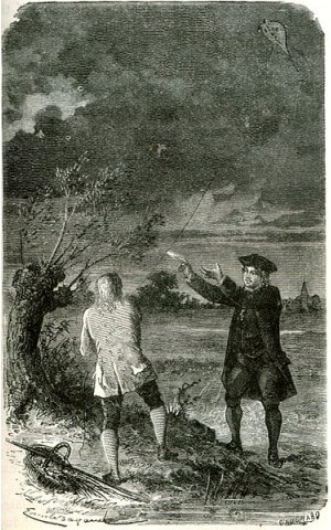
Engraving of Benjamin Franklin's kite-flying experiment
In 1733, the French chemist Charles François de Cisternay du Fay (1698-1739) had discovered the existence of two types of electricity, which he named "vitreous" and "resinous". The vitreous electricity was created by rubbing a piece of glass with silk, whereas the resinous electricity was created by rubbing a piece of amber with fur.
He found that two charged glass rods would repel each other. Similarly, two charged amber rods would also repel each other. A charged glass rod and a charged amber rod, on the other hand, would attract each other. He concluded that two objects charged with electricity of the same kind would repel each other, whereas two objects charged with electricity of different kinds would attract each other.
Franklin labelled the "vitreous" electricity as positive, and the "resinous" electricity as negative. This does indeed fit with our modern definition of positive and negative charge, since when glass is rubbed with silk, electrons are transferred from the glass to the silk, leaving the glass positively charged. Amber, on the other hand, will gain electrons when rubbed with fur and thus become negatively charged.
Franklin's choice of labels was probably purely arbitrary, even though it turned out to be correct. He made the erroneous assumption, however, that the flow of current was created by positive charge carriers migrating from the positive terminal of a circuit to the negative terminal.
We know today, of course, that the charge carriers in electrical circuits are in fact negatively charged electrons, and that they migrate in the opposite direction - from the negative terminal to the positive terminal. The electron, however, would not be discovered until the end of the nineteenth century. By that time, the convention established by Franklin (i.e. that current flows from positive to negative) was firmly entrenched.
The direction of current flow in an electrical circuit is often indicated on circuit diagrams with an arrow. The direction in which the arrow is pointing, unless otherwise stated, indicates the direction of conventional current flow (as defined by Franklin). In other words, the opposite direction to that in which the electrons are moving. You can think of it as the direction in which positive charge carriers would flow in the circuit if they existed.
Sometimes, it is useful to think about current flow in terms of the electrons that actually carry the charge in a circuit. To facilitate this, we can talk in terms of an electron current that flows in the opposite direction to conventional current in a circuit, i.e. from the negative terminal (or cathode) to the positive terminal (or anode).
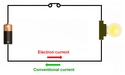
Conventional current vs. electron current
Voltage (or electromotive force) is the term used to describe the difference in charge (often referred to as the potential difference or voltage drop) between two points in an electric field or an electrical circuit. Voltage can be thought of as providing the force that pushes charge carriers (usually electrons) around a circuit to create current. The symbol used for voltage is usually an italicised upper-case V (for voltage) or E (for electromotive force).
Assuming the resistance in a circuit remains constant (we will talk in more detail about resistance shortly) then the amount of current flowing between two points in a closed circuit will vary with the amount of voltage applied across them. A large voltage will drive more current than a small voltage.
Earlier, we likened the flow of current in a circuit to the flow of water in a pipe. Staying with our water analogy, we can liken voltage to the pressure created by the water in a tank. Let's assume we have an arrangement like the one illustrated below, with a pipe draining water from a tank as before. The water pressure at the end of the pipe will depend on the total depth of the water (i.e. the depth of the water in the tank plus the vertical distance between the bottom of the tank and the pipe's outlet), and the diameter of the pipe.
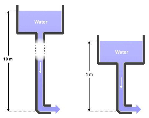
Water pressure is analogous to voltage
In the illustration above, water pressure can be likened to voltage. Assuming the diameter of the pipes is the same in both cases, the water pressure created by the left-hand tank will be much greater than that created by the right-hand tank. The difference in water pressure is due to the difference in the vertical distance between the end of each pipe and the water level in the tank that supplies it (i.e. ten metres as opposed to one metre).
In the same way, a ten-volt power supply creates a much bigger potential difference between two points in a circuit than a one-volt power supply would create between the same two points in the circuit, and will thus drive more charge carriers through the circuit, creating a large current.
The unit of voltage is the volt (symbol: V), named after the Italian physicist and chemist Alessandro Giuseppe Antonio Anastasio Volta (1745-1827), another pioneer in the study of electricity, who is credited with having invented the Voltaic pile (an early form of battery) in 1799. One volt is usually defined as:
". . . the difference in electric potential between two points of a conducting wire when an electric current of one ampere dissipates one watt of power between those points".
It can also be defined as the potential difference that will drive one coulomb of charge through a resistance of one ohm in one second.
Because voltage is essentially the difference in charge between two points, a voltage can exist even if there is no current flowing between the two points (as would be the case, for example, in an open circuit). In other words, an electrostatic field can exist between two points even if there is no movement of charge carriers between the two points. Current, on the other hand, cannot flow in the absence of a voltage.
The voltage supplied by a battery or other constant voltage source is a DC voltage, and produces direct current. The mains electricity coming into your home, by contrast, will almost certainly have an alternating voltage in which the polarity of the potential difference changes periodically (the polarity of mains electricity in most countries switches backwards and forwards with a frequency of either fifty or sixty cycles per second).
Resistance is the degree to which a material prevents (or resists) the movement of electric charge (and thus, by definition, the flow of current) through a circuit. The symbol normally used for resistance is an italicised upper-case R (for resistance). Materials that are good conductors of electricity have a low resistance, whereas materials that are poor conductors of electricity have a high resistance.
The cables carrying electricity around your home for lighting and power will probably be made of copper, which is a highly conductive metal. The insulating material surrounding these cables is usually made of a plastic material such as PVC (polyvinyl chloride), which has a very high resistance to electrical current.
Note that there is no such thing as a perfect insulator. Regardless of the resistance offered by an insulating material, if the voltage becomes large enough it will tear electrons away from the atoms within the material. These electrons will then become charge carriers. The voltage at which this occurs is usually referred to as the insulating material's breakdown voltage.
By the same token there is no such thing as a perfect conductor, in the sense that even highly conductive materials offer some resistance to the flow of charge (actually that's not entirely accurate - if you go on to study theoretical physics you will no doubt learn about superconducting materials that offer no resistance to the flow of electric current once they have been cooled to sufficiently low enough temperatures).
The resistance of a conducting wire in a circuit will depend on two things - the material from which the conducting wire is made, and its cross-sectional area (we will assume that the cross-sectional area of the wire is uniform throughout its length). To illustrate this, we can use our water analogy once more.
Let's assume that water is flowing out of two identical water tanks, through two pipes that are identical in every respect except for the diameter of the pipe (assume that the initial water level in each tank is the same), as illustrated below.
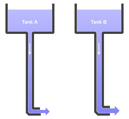
Water flows from each tank at a different rate
The water flowing from tank A is under the same pressure initially as that flowing from tank B, but must flow through a pipe with a smaller diameter that offers greater resistance to the flow of water. Water will thus flow more quickly from tank B than from tank A. In the same way, the resistance of the conducting wires in a circuit will depend on the diameter of the wire. The smaller the diameter, the greater the resistance of the wire.
The unit of resistance is the ohm (Symbol: Ω), named after the German physicist and mathematician Georg Simon Ohm (1789-1854) who, whilst carrying out research using the electrochemical cell invented by Volta and equipment of his own design, discovered the mathematical relationship between voltage, current and resistance known as Ohm's law (see below). The ohm can be formally defined as follows:
"An electrical resistance between two points of a conductor when a constant potential difference of one volt, applied to these points, produces in the conductor a current of one ampere, the conductor not being the seat of any electromotive force."
Ohm's law, as mentioned above, is named after George Ohm, who discovered the mathematical relationship between voltage, current and resistance. Ohm published his findings in 1827, in a paper entitled The Galvanic Circuit Investigated Mathematically. As Ohm himself put it:
"The amount of current flowing in a circuit made up of pure resistances is directly proportional to the electromotive forces impressed on the circuit and inversely proportional to the total resistance of the circuit."
Ohm's law essentially states that, at a given temperature, the current flowing between two points in a circuit is directly proportional to the voltage, and inversely proportional to the resistance, across those two points. When Ohm says "a circuit made up of pure resistances" he is referring to a circuit that does not contain inductors or capacitors. The resistance in the circuit is assumed to have a constant value.
Ohm's law tells us that the current I (in amperes) flowing through a circuit is simply the quotient of voltage V (in volts) and resistance R (in ohms). The mathematical expression of Ohm's law is therefore quite straightforward, and can be expressed as follows:
| I = | V |
| R |
It follows from the above that if we know the value of any two of the variables involved - voltage (V), resistance (R), or current (I) - we can calculate the value of the third (unknown) variable. The above formula will give us the current, for example, if both voltage and resistance are known. If the unknown variable is resistance, we can rearrange the formula as follows:
| R = | V |
| I |
And to find an unknown voltage, we use:
V = I · R
We perhaps misused the term "variable" with respect to resistance, since the value of resistance in a circuit does not usually change - unless of course the breakdown voltage is exceeded. Even minor variations due to variances in temperature are not usually significant, although the resistances of some electronic components can change over time, or through exposure to extreme environmental conditions.
An understanding of the relationship between voltage, current and resistance, which is described by Ohm's law, is a fundamental requirement for those wishing to study electronics or electrical engineering, and is also important for many other areas of study, including physics. One way of remembering Ohm's law is to memorise this simple graphic representation:
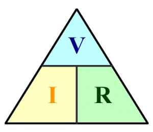
Graphical representation of Ohm's law
To use the Ohm's law triangle, we cover up the quantity we want to find the formula for (this goes on the left-hand side of the equals sign), and the apply the positional relationship between the remaining two quantities to determine what goes on the right-hand side of the equals sign.
To find the formula for current I, we cover up the "I" in the triangle, which gives us voltage "V" over resistance "R". To find the formula for resistance R, we cover up the "R" and are left with voltage "V" over current "I". To find the formula for voltage V, we cover up the "V" to leave current "I" multiplied by resistance "R".
The current produced by a battery is called direct current (DC) because it flows in one direction only and is driven by a constant voltage. The kind of electricity supplied to homes and businesses in most parts of the world, however, is called alternating current (AC), because both the direction of current flow and the voltage change periodically.
We'll start by thinking about a single cycle of an alternating current. During the first half-cycle, charge will move in one direction as voltage rises from zero to some peak value and then falls back to zero. During the second half-cycle, charge will move in the opposite direction as voltage rises from zero to a peak value of the same magnitude but opposite polarity and then falls back to zero.
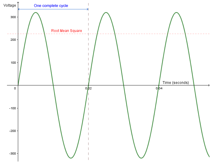
The voltage sine wave for a nominal 230 V AC mains supply
At the start, end, and mid-point of each cycle, the voltage is zero. The peak voltage at the mid-point of the first half-cycle, to which we attribute a positive value, is of equal magnitude but opposite polarity to the peak voltage at the mid-point of the second half-cycle, to which we attribute a negative value. The attribution of sign is somewhat arbitrary, but it represents the difference in the direction in which charge is moving.
The voltage sine wave for an alternating current is a plot of voltage against time, and is characterised by its amplitude (the maximum value it can take in either direction), its frequency (the number of complete cycles that occur per second), and its phase (or phase angle - more about that shortly). The voltage sine wave is defined by the following mathematical function:
V(t) = VP sin(2πft + φ)
where:
V(t) is the voltage (in volts) as a function of time
VP is the amplitude in volts
f is the frequency in hertz
t is the elapsed time in seconds
φ is the starting phase angle in radians
The phase angle can take any value between 0 and 2π radians (0-360°). When plotting a graph of AC voltage, the phase angle will determine at which point in the cycle we start to draw the sine wave. For the purposes of this discussion, we can assume that the phase angle is zero and effectively ignore it. Substituting in known values for our UK AC mains supply (and assuming a phase angle of zero), we get the following:
V(t) ≈ 324 sin (2π × 50 × t + 0)
Note that we have used the "approximately equal to" operator (≈) rather than the "equals" operator, because there will be some variance in the peak voltage over time. The frequency and voltage of the alternating current supplied to your home will depend to a large extent where in the world you live. In the United Kingdom, the electricity supplied to most homes has an RMS voltage of about two hundred and thirty volts (230 V), and a nominal frequency of fifty cycles per second (50 Hz).
You may have noticed that we used the term RMS voltage above, and that the figure quoted (two hundred and thirty volts) is far smaller than the peak voltage of three hundred and twenty-four volts. The reason for this is that, because the voltage is continually changing, we obviously don't have peak voltage all the time. In fact, the voltage is actually zero at two points in each cycle.
The effective value of a varying voltage (or current) is the equivalent steady DC value that has the same effect in terms of the power it supplies per unit time. When we talk about alternating current, therefore, we do not usually talk about peak voltage; rather we use an average value for the voltage produced over time. This is calculated using something called the Root Mean Square (RMS) function, which for a sine wave represents a value of about 0.707 of the peak voltage in either direction.
The RMS voltage for the UK domestic mains electricity supply is thus calculated as:
324 V × 0.707 ≈ 230 V
One question that occurs to many people is, why is electricity supplied to our homes as alternating current? Indeed, towards the latter half of the nineteenth century, opinion was divided over whether electricity should be generated as direct or alternating current. In the United States, the American inventor and businessman Thomas Alva Edison (1847-1931) developed his own distribution system for the delivery of direct current. A rival system based on alternating current was developed by the American entrepreneur and engineer George Westinghouse Jr. (1846-1914), who was heavily influenced by developments in Europe.
The rivalry between the two men was such that historians sometimes refer to it as the "War of the Currents". Suffice to say that Westinghouse was eventually able to emerge from this struggle triumphant, although he still faced a number of hurdles. These included stiff competition from General Electric, with whom Westinghouse was in dispute over a number of patents, as well as an unsuccessful takeover bid by General Electric.
The choice of alternating current over direct current for the large-scale distribution of power has to do with both the way in which electricity is generated, and the means by which it is distributed over long distances. Let's start by considering the way in which electricity is actually produced.
The English scientist Michael Faraday (1791-1867) discovered that a voltage could be generated in a length of conducting wire that was exposed to a moving magnetic field acting at right angles to the wire (i.e. so that the lines of magnetic flux cut across the conductor). If the wire can be coiled so that it is exposed to the same changing magnetic flux at several points along its length, the magnitude of the induced voltage will increase in proportion to the number of turns according to the following formula.
| e = N | dΦ |
| dt |
where:
e is the instantaneous voltage in volts
N is the number of turns in the wire coil
φ is the magnetic flux in webers
t Is the time in seconds
Faraday's discovery later proved to be the basis for a relatively straightforward method of generating electrical current that did not rely on the availability of one or more batteries. Devices that employs this principle to generate current are collectively called generators (no surprise there!), and include alternators (for the generation of alternating current) and dynamos (which produce direct current). We are primarily interested here in the alternator.
The alternator essentially consists of an electro-mechanical device in which mechanical power is used to rotate a wire coil past the poles of a permanent magnet (or vice versa) in order to generate a voltage in the wire. The mechanical power is usually supplied by some kind of turbine (a rotary mechanical device that extracts energy from the flow of a fluid - typically of gas, steam or water). The basic principle is illustrated below.
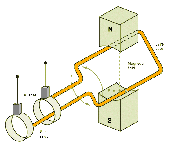
A simple alternator
If you study the diagram carefully, you should be able to see that the direction of current flowing through the wire loop will change direction each time the loop makes one half-turn, as it changes its orientation with respect to the direction in which the magnetic flux is acting. As you can see, each end of the loop is attached to a slip ring, each of which is in permanent sliding contact with one of two brushes. The brushes are connected to leads that allow the alternator to be connected to a load (the electrical component or system that is actually powered by the current generated).
A dynamo can generate DC current using almost the same arrangement. The most significant difference is that each end of the wire loop is connected to one half of a single ring called a commutator, the two halves of which are electrically isolated from one another. The principle is illustrated below. Each time one half of the commutator becomes fully engaged with one of the brushes, the direction of current flowing through the brush will be going in the same direction.
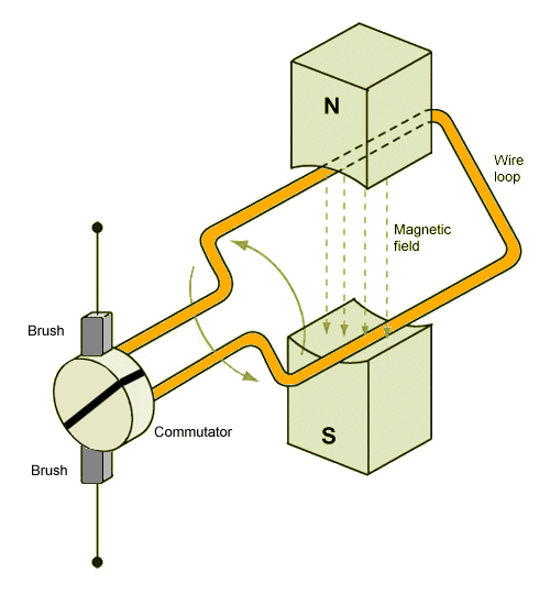
A simple dynamo
Although the current generated by our dynamo is no longer changing direction as it leaves the dynamo, there are some issues that we need to think about. For example, the voltage level is still going to change between zero and some peak value during each half-cycle. Also, as the commutator rotates it will continuously make and break the electrical contact with one or other of the brushes, resulting in sparking and the generation of heat.
The fluctuations in voltage can be resolved to a great extent by using multiple coils evenly spaced around the rotating shaft of the dynamo (this kind of assembly is called an armature), and commutators with multiple segments (one segment per coil). Each segment is connected to one end of two adjacent coils to provide electrical continuity throughout the armature assembly.
Clearly, generating direct current is not as straightforward as generating alternating current. The design of AC generators is generally simpler than that of DC generators, which means that AC generators are both easier and cheaper to manufacture than DC generators, and tend to be more reliable.
The other major advantage of AC current over DC current, as we mentioned earlier, is related to the distribution of electrical power. That is what you are using when you switch on a light, or boil a kettle, or start up your computer. Power P, in electrical terms, is the product of current I and voltage V:
P = VI
So, in order to satisfy demand, we need to ensure that sufficient power is delivered to the customer - wherever they may be - to meet all of their power requirements. According to our power equation, then for a given power requirement, increasing the voltage of the power transmission will result in a lower current. Lower currents mean that less power is lost, because it reduces the amount of heat dissipated in the power transmission lines due to resistance.
A high-voltage power transmission system is thus more efficient than a low-voltage system. At this point, however, many students are somewhat dismayed by the idea that increasing voltage will reduce current. Surely this can't be correct, since according to Ohm's law the current through a circuit is proportional to the voltage drop across the circuit? In order to understand how this works, we need to look at a device called a transformer.
Among his many other achievements, Michael Faraday discovered a phenomenon known as mutual inductance. We have already seen that a changing magnetic field cutting the turns in a wire coil can generate an alternating current in the coil, and that the magnitude of the induced voltage will be proportional to the number of turns in the coil. It is therefore not too surprising that, if we reverse the situation and place an alternating voltage across a coil, we will create a fluctuating magnetic field.
Suppose we now bring a second coil (let's call it the secondary coil) into close proximity with the first coil (which we'll call the primary coil). The changing magnetic field produced by the primary coil will generate an alternating current in the secondary coil. If the number of turns in each coil is the same, the induced voltage across the secondary coil will be of the same magnitude as the voltage across the primary coil.
If the number of turns in the secondary coil is less than the number of turns in the primary coil, the induced voltage in the secondary coil will be lower than the voltage in the primary coil. Conversely, if the number of turns in the secondary coil is greater than the number of turns in the primary coil, the induced voltage in the secondary coil will be higher than the voltage in the primary coil. This relationship can be expressed algebraically as follows:
| VS = VP | NS |
| NP |
where:
VP is the voltage across the primary coil
VS is the voltage across the secondary coil
NP is the number of turns in the primary coil
NS is the number of turns in the secondary coil
Mutual inductance thus gives us a means of "stepping up" or "stepping down" an alternating voltage. Since stepping up the voltage on a transmission line reduces current (we'll come back to this point in due course), we now have a means of distributing power over long distances using high-voltage transmission lines with minimal loss of power. The voltage can be stepped down again to usable levels by local sub-stations, increasing the current once more, and enabling power to be delivered to homes and businesses.
A device which steps the voltage of an alternating current up or down is called a transformer. The diagram below is a schematic view of a simple step-up transformer.
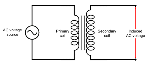
Schematic of a simple step up transformer
To get back to the question we asked earlier - i.e. how can we reduce current by increasing voltage - let's consider what we are actually doing, which is to transfer electrical power. We can't create power out of thin air. Therefore, in an ideal transformer (i.e. a transformer in which no power is lost), the power output from the secondary coil will be the same as the power input to the primary coil. In other words:
P = VP IP = VS IS
where:
P is the power supplied to the primary coil
VP is the voltage across the primary coil
IP is the current through the primary coil
VS is the voltage across the secondary coil
IS is the current through the secondary coil
The obvious implication here is that if the voltage across the secondary coil is greater than the voltage across the primary coil, then the current flowing through the secondary coil must be smaller than the current flowing through the primary coil. In order for Ohm's law to apply, the resistance across the secondary coil must be significantly greater than the resistance across the primary coil.
We mentioned above, however, that when Ohm says "a circuit made up of pure resistances" he is referring to a circuit that does not contain inductors or capacitors. Our transformer consists of two coils, and a coil, by definition, is an inductor (it is actually very rare for an AC circuit to be made up of pure resistances). In fact, when it comes to AC circuits, we usually talk about impedance rather than resistance.
Impedance is made up of both resistance (the intrinsic ability of a material to resist the flow of current) and something called reactance. The reactance in an inductor is called (surprise surprise) inductive reactance. Essentially, the magnetic field generated by an inductor (like the secondary coil in our transformer) generates a current in the coil that flows in the opposite direction to the current that generated the field in the first place.
It would probably be counterproductive at this stage to delve too deeply into the mathematical relationships at work here; suffice to say that increasing the number of turns on the secondary coil will increase the induced voltage across the coil, but it will also increase the reactance (and hence the impedance) of the coil, which will inhibit the flow of current.
The final point to make here is that only a fluctuating magnetic field can continuously generate current in a wire, and only a current that is constantly changing direction can generate a fluctuating magnetic field. A transformer is designed to work only with alternating current, and should never be connected to a DC power supply.
Today, it is possible to buy affordable, accurate, reliable and highly portable devices for measuring current, voltage and resistance in any D.I.Y. store. They are no longer solely used by scientists, but by electrical and electronics engineers, the manufacturers of electrical goods and electronic components, electricians, and members of the general public. Early attempts to build instruments for making electrical measurements, however, resulted in some fairly strange-looking and unwieldy devices.
Indeed, even following Volta's invention of the battery in 1800, there was little practical use for such devices. The earliest widespread use of electricity was probably in the telegraph system; even there, the measurement of voltage and current was only undertaken during activities involving maintenance or repair work. The situation changed towards the end of the nineteenth century with the emergence of the electric power industry, which brought with it the need for regular measurement of both voltage and current.
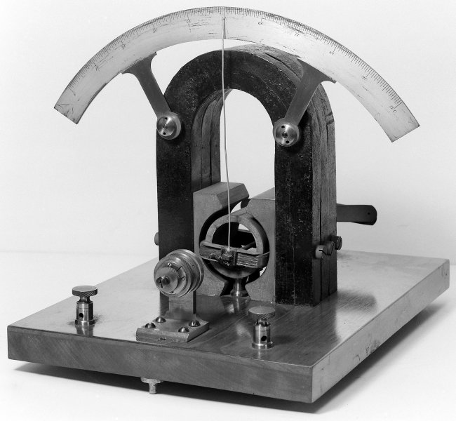
One of the earliest instruments used to measure current is an electro-mechanical device called a galvanometer - an early version of the modern instrument known as an ammeter (see below). The galvanometer was developed following an observation made in 1820 by the Danish physicist and chemist Hans Christian Ørsted (1777-1851) that the needle of a magnetic compass is deflected near a wire in which a current is flowing.
The first widely-used and reasonable accurate galvanometer was developed in 1882 by the French physician and physicist Jacques-Arsène d'Arsonval (1851-1940), with the assistance of the French electrical engineer Marcel Deprez (1843-1918). The d'Arsonval galvanometer consists of a light coil of wire suspended between the poles of a permanent magnet by a fine wire attached to each end of the coil.
The current to be measured is allowed to flow through the coil, producing a magnetic field that interacts with the magnetic field of the permanent magnet, causing the coil to rotate. A small mirror attached to the coil deflects a beam of light to indicate the degree to which it has turned, allowing the amount of current flowing through the coil to be determined. The sensitivity of d'Arsonval's original instrument was such that it could detect a current of ten microamperes (10 µA).
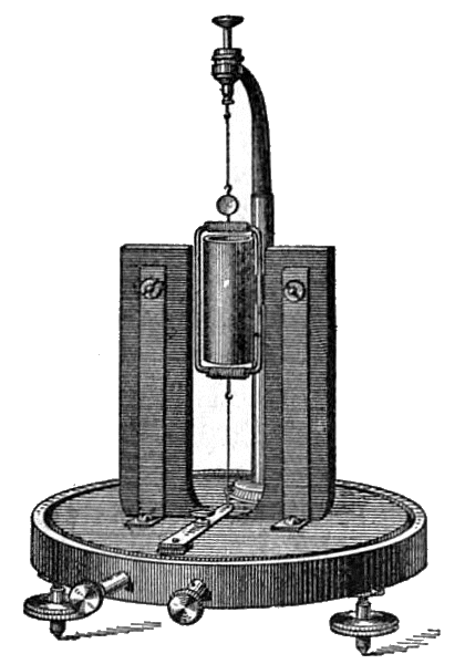
Engraving of an early D'Arsonval galvanometer
Image: The New International Encyclopaedia (circa 1903)
A significant improvement to d'Arsonval's design was made by the English-born American chemist Edward Weston (1850-1936). Instead of suspending the coil on a wire - which must also provide the necessary torque to restore the coil to its original position on completion of a reading - Weston mounted his coil on a pivot, and used spiral springs similar to those used in a wristwatch to provide both the necessary restoring force and the electrical connections to the coil. The coil is attached to a pointer that traverses a calibrated scale on the instrument to indicate the current, as illustrated below.
By 1888, Weston had patented his design and began manufacturing and marketing compact and portable versions. He called his product the "Portable Instrument" on the basis that it could be transported from place to place and used just about anywhere, unlike its predecessors which were largely confined to laboratory use, and were not easily transported. Weston's design is essentially the same as that found in the analogue instruments still in use today.
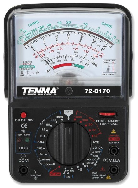
Instruments for measuring current, voltage and resistance are called ammeters, voltmeters and ohmmeters respectively. However, the most widely used instrument for measuring electrical quantities today is called a multimeter, because it combines the functionality of all three instruments. Although most multimeters are digital, analogue multimeters are useful when we want to see the degree to which a signal is fluctuating because the operator can see the needle swing (they can also be used to measure voltage even if the battery is dead, unlike a digital multimeter).
The analogue multimeter pictured above has a voltage measurement range of six hundred millivolts to one kilovolt DC (600 mV - 1 kV) or twelve volts to one kilovolt AC (12 V - 1 kV), a resistance measurement range of one ohm up to ten kilohms (1 Ω - 10 kΩ), and a current measurement range of one hundred and twenty microamperes up to ten amperes (120 µA - 10 A).
The analogue multimeter is essentially a galvanometer, and uses the d'Arsonval moving coil principle to measure current. The instrument is connected to the circuit being tested in series, so that it effectively becomes part of the circuit. In order to measure current accurately, the multimeter should not disturb (i.e. significantly increase the overall resistance of) the circuit. Ideally, its internal resistance should be zero.
Since the instrument's moving coil and internal circuitry will have a significant resistance, the design of the ammeter circuit must compensate for this. In the arrangement shown below, the low-value resistor RP (sometimes referred to as a shunt resistor) is placed in parallel with the galvanometer resistance RG , enabling most of the current to bypass the coil and limiting the extent to which the circuit is disturbed. The current flowing through the coil is just a tiny fraction of the total, and it is this current that is actually measured.
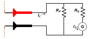
The ammeter is connected in series with the circuit under test
When two or more resistances in a circuit are in parallel, the voltage drop across them will be the same. Since the value of both the galvanometer resistance RG and resistor RP are known, and the current IG flowing through the galvanometer coil can be measured, the total current IC flowing in the circuit can be determined using Ohm's law (see below). The value of resistor RP for a given current range is chosen so that the position of the needle on the ammeter scale gives an accurate indication of the total current.
| IC = IG × | ( | 1 + | RG | ) |
| RP |
In order to measure the voltage drop across a circuit component, the meter is connected in parallel with the component as shown below. For the voltmeter circuit, a high-value resistor is placed in series with the galvanometer resistance RG . The series resistor allows only a tiny amount of current to flow through the coil so that, limiting the extent to which the circuit is disturbed.
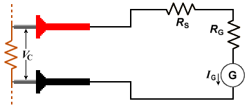
The voltmeter is connected in parallel with the circuit element under test
Because the galvanometer is in parallel with the circuit component being tested, the voltage drop across it will be the same as the voltage drop we want to measure. The value of both the galvanometer resistance RG and resistor RS are known, and the current IG flowing through the galvanometer coil can be measured. Voltage VC is related to current IG in accordance with Ohm's law, as shown below. The value of resistor RS for a given voltage range is chosen so that the position of the needle on the voltmeter scale gives an accurate indication of voltage.
V = IG × (RS + RG )
To measure the resistance across a circuit component, the component must be removed, or at least isolated from, the rest of the circuit. The meter is then connected to the component's terminals as shown below. For the ohmmeter circuit, a calibration resistor RO is placed in series with the galvanometer resistance RG .
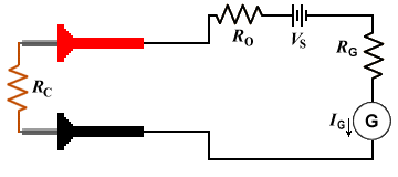
The ohmmeter is connected across the terminals of the component to be tested
An internal voltage source drives a small current through the ohmmeter circuit. The value of both the galvanometer resistance RG and resistor RO are known, as is the supply voltage, and the current IG flowing through the galvanometer coil can be measured. The component resistance RC can again be determined using Ohm's law (see below). The value of resistor RO for a given resistance range is chosen so that the position of the needle gives an accurate indication of the resistance on the ohmmeter scale.
| RC = | VS | - (RO + RG ) |
| IG |
Many analogue multimeters can also measure AC current and voltage. In these instruments, a rectifier circuit is used to convert the input to a DC current before it reaches the galvanometer coil.
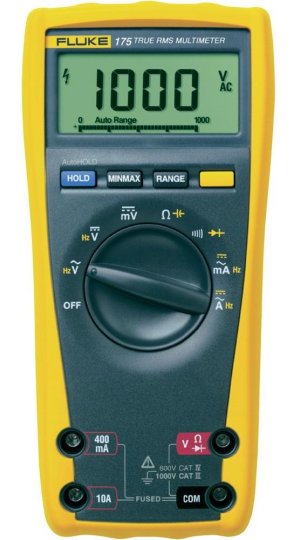
The digital multimeter (sometimes abbreviated as DMM) provides the same functionality as an analogue multimeter. One obvious difference is that the digital multimeter has a digital display instead of an analogue display. It also functions somewhat differently internally. Instead of measuring current using a moving coil, the digital multimeter measures voltage using a special kind of analogue to digital converter (ADC) called a successive approximation register (SAR).
The digital multimeter pictured above can measure AC or DC voltages of up to one kilovolt (1 kV) with a maximum resolution of one millivolt (1 mV), has a resistance measurement range of up to fifty kilohms (50 kΩ) with a maximum resolution of one tenth of an ohm (0.1 Ω), and can measure AC or DC currents of up to ten amperes (10 A) with a maximum resolution of one hundredth of a milliamp (0.01 mA).
The block diagram below illustrates how the SAR operates. The analogue value of the voltage to be measured (VIN ) is acquired by the sample and hold circuit (S/H). At the same time, an internally generated reference voltage (VREF ) with a known value is fed into a digital to analogue converter (DAC). The analogue values from the sample and hold circuit and the DAC are then sent to an analogue voltage comparator.
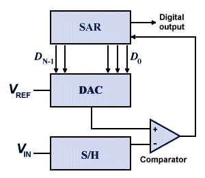
Block diagram of SAR analogue to digital conversion process
To start the process, the SAR's control circuitry sets the most significant bit (MSB) of the DAC to one, and all the other bits are set to zero. This forces the DAC to output a voltage that is one half of the actual reference voltage. The analogue voltage comparator then compares the two signals, and the result of the comparison is sent to the SAR. The SAR's MSB is set to one or zero, depending on whether VIN is higher or lower than VREF , respectively. If VIN is greater than VREF , the DAC's most significant bit remains high (i.e. one), otherwise it will be set to zero.
In the next iteration of the cycle, the DAC's second left-most bit is set to one, forcing the DAC's output to be either three quarters or one quarter of the total reference voltage (depending on the outcome of the first comparison). The comparator then compares the input voltage with the reference voltage once more, and sends the result to the SAR, which sets its next most significant bit accordingly.
As the process continues, the DAC's output voltage is adjusted up or down by successively smaller values, as the SAR homes in on an increasingly precise binary representation of the input voltage. The number of comparisons made (and thus the degree of precision achieved) depends on the number of bits available in the successive approximation register - sometimes called its resolution - to hold the result of the comparison.
As with the analogue multimeter, the digital multimeter must be connected in series with a circuit to measure current. A shunt resistor is used to ensure that only a tiny fraction of the input current actually passes through the SAR circuit, for which the resistance is known. The total circuit current can be determined from the measured voltage according to Ohm's law, using a similar formula to the one we saw above.
Resistance is measured in much the same way as with an analogue multimeter. The component is removed or isolated from the rest of the circuit, and the meter is connected to the component's terminals. An internal source drives a small current with a known value through the component, and the voltage drop across it is measured. The component's resistance is determined using Ohm's law.
Like analogue multimeters, most digital multimeters can also measure alternating currents and voltages if a suitable rectifier circuit is used to enable the multimeter to determine the average or peak value of the input voltage, from which the RMS value will be derived using the appropriate conversion factor.
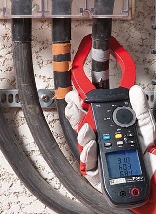
A multimeter is used in the manner described above where the amount of current involved is relatively small (i.e. ten amperes or less). Sometimes, however, we may need to measure much larger alternating currents. In cases like this, using a multimeter is not an option, and we must turn to an instrument called a clamp meter.
Originally created to measure large currents without disturbing the circuit, many modern clamp meters can provide services similar to those provided by a digital multimeter. A typical clamp meter has a hinged and spring-loaded jaw that can be clamped around a current-carrying cable, as shown in the illustration above. Clamp meters can measure currents of hundreds or even thousands of amperes. In addition, because it is not necessary to connect them to the circuit or to shut off the current in order to take a measurement, they are both safe and convenient to use.
The moving charge carriers (i.e. electrons) in a current-carrying cable generate a magnetic field that operates at right-angles to their direction of motion. The clamp meter works by measuring the magnetic field generated by the current flowing through the cable, and thus requires no direct contact with the circuit itself. The precise way in which this is achieved depends on the type of clamp meter used. Some clamp meters use a simple transformer action, others take advantage of a phenomenon known as the Hall effect.
The transformer action clamp meter can only measure alternating current. Any cable carrying an alternating current will act like the primary winding in a transformer. The jaws of the clamp meter are made of ferrite iron, and have a secondary winding hidden beneath the plastic covering, like the secondary winding found in a transformer.
The alternating current in the cable creates a changing magnetic field that induces a much smaller alternating current in the secondary winding. It is this induced current, which is proportional to the current flowing in the cable, that is measured by the clamp meter. The value sent to the digital display is calculated using the appropriate conversion factor.
A Hall effect clamp meter can be used to measure both alternating and direct current. The Hall effect was discovered by the American physicist Edwin Herbert Hall (1855-1938). He found that a voltage was produced across an electrical conductor traverse to a current flowing in the conductor, and to a magnetic field acting at right angles to the current. The voltage produced depends on factors such as the current flowing in the conductor, the strength of the applied magnetic field, the dimensions of the conductor, and the material from which the conductor is made.
The Hall effect clamp meter incorporates a Hall effect sensor - essentially a thin strip of metal to which a small current is applied. In the presence of the magnetic field surrounding a current-carrying conductor, a voltage develops across the strip. This voltage can be measured by the clamp meter, enabling it to determine the strength of the magnetic field generated by the current-carrying cable, and thereby the current flowing in the cable.