| Author: | |
| Website: | |
| Page title: | |
| URL: | |
| Published: | |
| Last revised: | |
| Accessed: |
Like most of the quantities we will talk about in this section, temperature - or to be precise thermodynamic temperature - is one of the base quantities defined by the International System of Units. The internationally agreed base unit for temperature is the kelvin, named after the Irish mathematical physicist and engineer William Thomson (1824-1907). Thompson earned the title 1st Baron Kelvin in 1892, partly in recognition of his achievements in the field of thermodynamics, and partly due to his opposition to Irish home rule.
The SI unit for heat energy (or work or just energy) is the joule, although we sometimes refer to a unit of heat used in the centimetre-gram-second (CGS) system of physical units called a calorie. One calorie represents the amount of heat energy required to increase the temperature of one gram (one cubic centimetre) of pure liquid water by one degree Celsius (1 °C), or that is lost by one gram of pure liquid water as its temperature decreases by one degree Celsius.
The concept of heat is generally associated with that of temperature, and rightly so. They are of course closely related, but they are not the same thing. We often talk about a "heat wave" when temperatures are higher than normal in the summer, but even in the depths of winter, when temperatures fall below the freezing point of water, our environment is far from being devoid of heat. If it were, none of us would be here to talk about it. So what is the difference between temperature and heat? We'll come back to that question shortly.
Man has always been aware of the fact that some things, such as fire, are very hot, and other things, like ice and snow, are very cold. The human body is very sensitive to even relatively small changes in air temperature, and we can readily determine how hot or cold an object or substance is in relative terms simply by touching it. As you are no doubt aware, however, many things are so hot (or so cold) that touching them would yield no useful information about their temperature, and could even result in serious injury. Touching a hot iron, for example, even for a moment, can give you a nasty burn (I speak from experience). Nevertheless, we have to have some way of determining temperature; the success of many modern industrial, scientific and commercial endeavours is dependent on this ability.
Measuring temperature is not as easy or straightforward as measuring something like length or mass. That said, we have been using high-temperature processes for thousands of years to create tools, weapons, and other artefacts, despite the absence of any meaningful temperature scale.
In order to make metal implements from bronze (a metal alloy consisting of about eighty-eight per cent copper and twelve per cent tin), it was necessary to heat the metals to a very high temperature so that they would melt and form an alloy. The molten metal could then be poured into a mould to form a casting. At lower temperatures, the casting would harden, but would still be malleable enough to be shaped by hammering.
To put things into perspective, the Bronze Age began sometime around 3300 BCE. It is generally considered to have ended around 1200 BCE, when it was succeeded by the Iron Age. It was not until the latter half of the 16th century CE, however, that man started to develop instruments that could actually measure temperature with a reasonable degree of accuracy. It was not for want of trying; efforts to establish some kind of yardstick for measuring temperature date back at least as far as the second century CE.
The Greek physician, surgeon and philosopher of the Roman Empire Aelius Galenus or Claudius Galenus (129 CE - circa 200 or 216 CE), probably better known as Galen Of Pergamon, made a great number of contributions in the fields of human anatomy and medicine. He also made one of the first attempts on record, in 170 CE, to create a "neutral" temperature standard by mixing equal amounts by volume of ice and boiling water. From this standard, he derived four degrees of heat that lay above his neutral temperature, and four degrees of cold that lay below it.
It was not until the late sixteenth century CE, however, that the first thermometer appears in historical records. Prior to this, temperature measurement seems to have been largely based on observation, in the sense that wax would melt, water would boil, and various metals would start to glow (or even melt) when sufficient heat was applied. Even so, there was no real temperature scale, and no reliable way to measure the temperature at which such events occurred.
The credit for the invention of the thermometer is often given to the Italian astronomer, physicist, engineer, philosopher and mathematician Galileo Galilei (1564-1642). The device was invented in around 1592, and was known as a thermoscope or air thermometer. The thermoscope consisted of a long glass tube, open at one end and opening into a bulbous enclosure at the other end. The open end of the tube is immersed in a vessel containing water as shown in the illustration below. If some of the air in the tube is allowed to escape, the lower part of the tube becomes partially flooded. If the temperature of the bulb is increased, the air inside it will expand, forcing some of the water out of the tube. Conversely, if the temperature of the bulb cools, the air inside it will contract, allowing more water to enter the tube.
The level of the water in the tube will rise or fall, depending on the temperature of the air inside the bulb. There was no scale on the glass tube, and the instrument would not have been particularly accurate anyway because it is affected by changes in atmospheric pressure, but it was a step in the right direction. Indeed, the general principle on which it is based (noting the changes in the volume of a gas or a liquid in a tube due to changes in temperature) is essentially the same as that of a modern glass thermometer.
Galileo's thermoscope (circa 1592)
The Italian physician Santorio Santorio (1561-1636), best known for his studies of human physiology, improved on the design of the thermoscope in around 1612. In his version, a graduated scale was added to the glass tube, and he used the device to measure variations in human temperature with some success. Although the device was still not particularly accurate, it could be used to detect, fairly reliably, whether or not a patient had a fever.
The next major advance is credited to the Italian Ferdinand II de' Medici (1610-1670), Grand Duke of Tuscany from 1621 until his death. He had a lifelong fascination with new technology, and was responsible for the construction of the first sealed thermometer in 1641. His thermometer was a glass tube with a bulb at one end, similar in shape to Galileo's, but positioned so that the bulb was at the bottom end of the tube. The bulb was filled with coloured alcohol, and the open end of the tube was sealed. The alcohol level in the tube would move up or down as the temperature changed, causing the liquid to expand or contract. The graduations on the tube allowed the temperature to be read, although there was still no standardised temperature scale against which these graduations could be calibrated.
Even though still not particularly accurate by today's standards, Ferdinand's device had several advantages over its predecessors. The use of a sealed tube meant that the device was portable. Furthermore, it significantly reduced the effect of variations in atmospheric pressure on the accuracy of readings. The use of alcohol meant that the device could be used at lower temperatures, since the freezing point of alcohol is considerably lower than that of water. And of course the coloured alcohol was much easier to see than water, making it easier to take temperature readings.
During the first part of the eighteenth century, a number of temperature scales evolved. The problem now, however, was that there were simply far too many different temperature scales in use. Among those trying to make sense of this somewhat chaotic situation was the Polish-Dutch engineer, physicist and glass-blower Daniel Gabriel Fahrenheit (1686-1736). Fahrenheit had learned how to calibrate thermometers from the Danish astronomer Ole Rømer (1644-1710), who had developed one of the first temperature scales (the Rømer scale).
Rømer based his scale on the proposal made by the English polymath Robert Hooke (1635-1703) for a temperature scale that used the freezing point of water as its zero point, but he realised that at least two fixed points would be needed in order to allow interpolation between them. On Rømer's scale, the freezing point of water was designated as seven-point-five degrees (7.5°). For the second fixed point, he chose the boiling point of water, which he designated as sixty degrees (60°).
From 1708 to 1724, Fahrenheit produced a number of thermometers based on Rømer's temperature scale. Although Fahrenheit refused to disclose the exact details of his calibration methods, he is known to have used the melting point of a mixture of sea salt, ice and water as one of his calibration points, and the temperature of a healthy human being as another. He improved the design of the instrument itself by replacing the bulb-shaped reservoir with a cylindrical reservoir, and used mercury instead of alcohol (the rate of thermal expansion of mercury is significantly more linear than that of alcohol). For the main body of the thermometer, he used a fine capillary tube. The thermometer was partially filled with mercury, and then heated so that the mercury would expand and force all of the remaining air out of the tube, which was then sealed.
Fahrenheit was obviously not happy with Rømer's temperature scale, as he subsequently created his own scale in which the freezing point of water was set at thirty two degrees (32°), and the boiling point of water at two hundred and twelve degrees (212°). The interval between the two points was thus exactly one hundred and eighty degrees (180°) on Fahrenheit's new scale. Note that the freezing point of water was originally set at thirty degrees (30°), but that was for salt-water. The freezing point of pure water is (approximately) two degrees higher. The Fahrenheit temperature scale was widely used in the UK until relatively recently, and is still used in the United States.
The temperature scale most widely used today (outside of scientific circles) is the Celsius temperature scale, named after the Swedish astronomer, physicist and mathematician Anders Celsius (1701-1744). Celsius set the zero point of his temperature range to the so-called "steam point" of water (essentially, its boiling point). He designated the melting point of pure water ice as the second anchor point in his temperature scale, and divided the interval between them into one hundred one-degree intervals. The scale was later inverted so that the melting point of water ice became zero degrees, with the boiling point of water set to one hundred degrees (100°), which seems far more logical.
The Celsius temperature scale has in the past often been referred to as the centigrade temperature scale because it divides the interval between the melting point of ice and the boiling point of water into one hundred equal parts. The name Celsius has been the preferred name since 1948, however, when it was officially adopted by an international conference on weights and measures.
The exact nature of heat has been a question that has occupied scientists for centuries, and attempts to define it have resulted in a number of theories being put forward. By the middle of the nineteenth century, the predominant theory appears to have been the Caloric Theory. In this theory, heat was an unseen physical entity - a somewhat mysterious fluid known as caloric. One of the main proponents of this theory was the French noblemen and chemist Antoine Lavoisier (1743-1794), an influential figure in the history of both chemistry and biology. He theorised that "caloric" manifested itself in one of two forms. Latent caloric was stored in combustible materials. This latent caloric, he reasoned, was released when such materials burned, releasing caloric to the immediate environment in a form that was observable through a change in the temperature of that environment.
Heat is thus described as a physical substance which can change its form, but must otherwise be conserved. If heat is released by some object or material, it must be gained by another object or material, and the overall amount of heat remains constant. There are some rather obvious problems with this theory, however. If heat is a physical substance that can be transferred from one object to another, there must surely be some accompanying transfer of mass. This would appear to be supported by the fact that, when a combustible material such as wood or coal burns, it invariably loses some mass to the environment. But what about any nearby objects that increase in temperature as a result of the combustion? According to caloric theory, they should gain "caloric", and therefore gain some mass.
The many accomplishments of British scientist Benjamin Thompson (1753-1814) - later Count Rumford - included designing warships for the British Navy during the American War of Independence. He wrote a scientific paper, published in 1798, that challenged the assumptions of caloric theory and sowed the seeds of a revolution in the field of thermodynamics. Having spent a number of years in the service of the Bavarian government, including a spell as Army Minister, his activities included overseeing the boring out of cannon barrels at the arsenal in Munich.
His observations there led him to conclude that, despite the amount of heat generated during this process (subsequently immersing the cannon barrels in water would eventually heat the water to boiling point), the cannon and the material removed from them did not undergo any chemical or physical change that would support the idea of some unseen substance (Lavoisier's "caloric") being transferred from the canon to the water. And, far from being a conserved quantity (which surely implies that the cannon must contain some fixed amount of latent caloric), Thompson noted that heat appeared to be generated at a continuous rate for as long as the boring process continued.
Thompson concluded that the heat generated by the boring process must have some mechanical explanation, and that it was in some way related to motion. He theorised that continuous mechanical action would produce heat indefinitely. He correctly identified the cause of the heat in the boring process as friction between the boring tool and the cannon. His 1798 paper rejected caloric theory, putting forward instead the view that heat was generated by the motion of atoms.
Although Thompson seems to have been content to let the matter lie there, the story continues with the work of the English physicist James Prescott Joule (1818-1889), after whom the SI derived unit of energy is named. Joule, who would later work with William Thompson (Lord Kelvin) to develop the Kelvin temperature scale, performed various experiments that established a relationship between heat and mechanical work. The illustration below shows the apparatus he used in one of his experiments. In this experiment, Joule used a weight suspended from a pulley to turn a spindle. A pair of paddles was attached to the bottom end of the spindle, which was mounted within an enclosure that had been filled with water.
Engraving of James Joule's apparatus for measuring the mechanical equivalent of heat, circa 1869
The work carried out by the weight as it descended under the influence of gravity, i.e. turning the paddles, resulted in an increase in the temperature of the water. Joule was able to show that the amount of heat energy gained by the water was directly proportional to the amount of work done by the weight, and further experiments confirmed these findings. Joule's theories about heat struggled to gain acceptance initially because they contradicted the widely accepted caloric theory. When he presented his results at a meeting of the British Association for the Advancement of Science in 1843, for example, his ideas got a somewhat less than enthusiastic reception.
The French physicist and engineer Nicolas Léonard Sadi Carnot (1796-1832), sometimes known as the father of thermodynamics, had certainly been a believer in caloric theory. Yet despite his support for an essentially flawed concept, his studies of heat as it related to the efficiency of various forms of "heat engine" was influential on the work later done by William Thompson (Lord Kelvin) and others in formulating the first law of thermodynamics. In 1824, Carnot published his Reflections on the Motive Power of Fire - apparently his only publication, and one which received little attention during his lifetime - in which he outlined his theories on the maximum efficiency of heat engines.
A heat engine is an engine that converts heat energy into mechanical energy so that it can do some form of mechanical work. Examples include steam engines and internal combustion engines. By the time Carnot published his paper, steam engines had already been in widespread use for about a century, and there were even crude forms of the internal combustion engine in existence. Even so, heat engines had not been the subject of any significant scientific study. Carnot was curious about the amount of work that could be produced by a heat source, and the degree to which the working fluid used in the heat engine (i.e. steam or some other fluid or gas) affected the efficiency of the heat engine.
Although Carnot's paper covers a number of topics, the most important idea presented therein was the abstract representation of a heat engine as a thermodynamic system. The physical implementation and specific design features of the heat engine are ignored. This rather conveniently allowed Carnot to ignore the loss of efficiency encountered in a real heat engine due to the friction between moving parts and the inevitable conduction of heat between physical engine components operating at different temperatures, both of which create a significant loss of efficiency in a real engine. Carnot's idealised heat engine thus achieves the maximum possible efficiency. Carnot states:
"The production of motive power is . . . due in steam engines not to actual consumption of caloric but to its transportation from a warm body to a cold body. In the fall of caloric, motive power . . . increases with the difference of temperature between the warm and cold bodies . . ."
The motive power generated by the ideal heat engine, and thus its efficiency, is presented as being solely a function of the difference in temperature between two heat reservoirs. Caloric is transported from a hot body to a cold body, in a process that involves neither friction nor the conduction of heat. Carnot concluded, essentially correctly, that the choice of working fluid has no bearing on the maximum efficiency attainable:
"The motive power of heat is independent of the agents employed to realize it; its quantity is fixed solely by the temperatures of the bodies between which is effected, finally, the transfer of caloric."
Carnot further proposed that, for an idealised heat engine, the whole process could be reversed, with no loss of caloric. In other words, reversing the motion of the engine (this would involve something doing work on the engine rather that the engine doing work on something) would result in the transfer of the same amount of caloric between the heat reservoirs, this time in the opposite direction. A cycle of this kind, in which a thermodynamic system undergoes a number of different states and is eventually returned to its original state, is commonly referred to as a Carnot cycle. The concept is today referred to as thermodynamic reversibility.
In 1847, William Thompson, or Lord Kelvin as he was later titled, attended another meeting of the British Association for the Advancement of Science in which James Prescott Joule attempted to discredit the Caloric theory and put forward his own ideas about the relationship between heat and mechanical work. Although not rejecting Joule's ideas outright, Thompson was sceptical; he was essentially a supporter of Caloric theory, which seemed to be supported by the work of Carnot, with which Thompson was familiar. Thompson was convinced that there must be some lowest temperature (absolute zero) that would be attained by a substance or material that had transferred all of its available caloric to some other substance or material.
Nevertheless, Thompson was obviously beginning to have some doubts about the validity of caloric theory. In one of his papers, he specifically refers to Joule's "very remarkable discoveries". The publication was later read by Joule himself, leading to correspondence between the two scientists. As a consequence, Thompson began to question Caloric theory and the ideas put forward by Carnot, and became more receptive to the idea that heat was a form of motion. Between 1852 and 1856, he collaborated with Joule to investigate the idea further. This collaboration would eventually lead to the acceptance of Joule's ideas by the scientific community.
The idea that heat and mechanical work were equivalent, however, had first appeared publicly in 1842 in the pages of the German publication Annalen der Chemie, a well-established and respected journal in the field of organic chemistry. The article in question was written by the German physician and physicist Julius Robert von Mayer (1814-1878) who had developed his ideas independently of Joule. Joule's paper The Mechanical Equivalent of Heat had not been published until 1845. There ensued a somewhat undignified dispute over who should actually get the credit for the discovery, into which a number of other scientists were dragged, Thompson included. It is probably fair to say, however, that while Mayer certainly published first, Joule provided the most convincing experimental results.
Thompson was meanwhile developing his own ideas on the formulation of an absolute temperature scale. He initially based his work on Carnot's theories on the motive power of heat, reasoning that if the amount of caloric available to a given system were finite, then exhausting that system's caloric would leave it at some lowest possible temperature (absolute zero). When he began to have doubts about the validity of Carnot's theories, however, he began to look at the work done earlier by Guillaume Amontons, Jacques Alexandre César Charles, and Joseph Louis Gay-Lussac (see below) on the relationship between temperature and pressure in an ideal gas. This work not only indicated that there was some nominal absolute zero temperature, but predicted a value for it that we now know to be fairly accurate.
The history of the scientific study of heat and the measurement of temperature is a long and complex story in which Joule and Thompson made significant contributions. The story has continued thanks to the efforts of many well-known and not so well known scientists. Because of their work, we know far more today about the nature of heat, and can measure temperature extremely accurately. Nevertheless, the acceptance by the scientific community of Joule's ideas - that work and heat were equivalent - and the establishment of a reliable absolute temperature scale by Lord Kelvin were milestones that paved the way for much of the work that would follow.
The terms temperature and heat both relate to energy. We should probably start by talking about what heat is, for reasons that will hopefully become apparent as we progress. You will no doubt already know that everything we can see around us in the physical world is made up of tiny building blocks called atoms, and that two or more atoms can join together to form more complex building blocks called molecules.
The atoms and molecules that make up any object or substance are constantly in motion. Consequently, they have a certain amount of kinetic energy. Kinetic energy is the energy that an object possesses due to its motion, and is defined as the work that must be done on an object in order to accelerate it from rest to its current velocity. The amount of energy the object has will not change unless its speed changes. In order to relinquish its energy and return to a state of rest, the object must do a certain amount of work. The same amount of work, in fact, that had to be done on it in the first place in order to accelerate it from a state of rest to its current speed.
There are two things to note here before we proceed. First, the amount of work needed to accelerate any object to a given velocity will depend on the mass of the object. The more mass the object has, the more work it will take to accelerate it to the specified velocity. Second, although it is possible for atoms and molecules to achieve a very low energy state, they can never be completely at rest. One of the things we have learned from quantum mechanics (which we are not going to get into here) is that even in its lowest possible energy state, an atom has something called zero-point energy. This energy manifests itself as vibration, which is itself a form of movement. An atom can never be completely at rest.
At this point it might be tempting to think that heat is simply the kinetic energy possessed by a body, but it's not quite as simple as that. Kinetic energy is . . . well, kinetic energy. Heat is something else. In fact, heat is the transfer of kinetic energy from one object or substance to another object or substance - or from an energy source to an object or substance. This is a distinction that is often poorly understood. People often use the term "heat" or "heat energy" to refer to the kinetic energy contained by a body or substance. Sometimes it's just more convenient to think of it in that way.
It is often claimed, by those wishing to make a point about the difference between heat and temperature, that a massive but relatively cold object like an iceberg contains far more heat than a far less massive but much hotter object like a kettle full of boiling water, even though the temperature of the iceberg will be considerably below that of the kettle. Although this kind of comparison serves to make the point that heat is not the same thing as temperature, it is not strictly correct. What is true is that an iceberg contains far more kinetic energy than a kettle full of hot water.
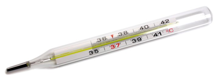
We'll come back to the point about heat being the transfer of kinetic energy shortly. Let's think instead for the moment about how we define temperature. In everyday terms, we can think of temperature as a measure of the "hotness" or "coldness" of something. You have no doubt had your temperature taken at some point in your life. You may even have taken someone else's temperature. This is usually achieved using a thermometer (a common instrument for measuring temperature). It doesn't tell you how much kinetic energy your body possesses at the moment. But what does it tell you?
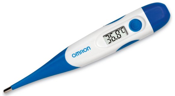
A digital thermometer of the type found in many homes
Temperature is, in fact, a measure of the average kinetic energy of an object or substance. As such, it relates directly to the speed at which the molecules in the object or substance are moving around. A thermometer cannot measure that energy directly. What it actually measures is the ability of the object or substance to transfer kinetic energy. In order to explain how a thermometer works, we have to refer to the principles of thermodynamics (which we'll talk about in more detail elsewhere).
The particular principle in which we are interested says that if two objects at different temperatures (i.e. that have different average kinetic energies) are in contact with one another, energy will be transferred (as heat) from the hotter object to the colder object, until both objects have the same average kinetic energy and achieve thermal equilibrium.
We see examples of this in our daily lives all the time. If you leave a cup of tea or coffee on your kitchen worktop for half an hour or so, it will gradually cool down. Eventually it will reach the same temperature as its surroundings (room temperature - whatever that happens to be in your kitchen). You can easily detect the fact that it has cooled when you pick it up, because it will feel considerably cooler than when you put it down.
What is not so obvious is that the energy lost from the cup has been transferred to its surroundings. You certainly won't be able to detect any change in the temperature in your kitchen, because it's not going to get significantly warmer. When you think about it, this makes sense, because we already mentioned that the work that must be done in order to increase the kinetic energy of an object is related to the object's mass. If you think of your kitchen as an object (or more realistically as a collection of objects), it has many hundreds or probably even thousands of times more mass than the cup and its contents.
One final point should serve to emphasise the difference between heat and temperature. If we make three cups of tea or coffee at exactly the same time, using water just boiled in the same kettle, we could reasonably expect them to have the same initial temperature. Furthermore, if the cups are all the same size, we could also reasonable expect them to contain the same amount of heat energy. But what if one of the cups is big, one medium sized, and one small?
Given the relationship between the mass of a body and the amount of energy required to raise its temperature by one degree, we can safely assume that the largest cup will initially contain more heat energy than the medium-sized cup, which will in turn initially contain more heat energy than the small cup. And yet, at least to start with, they will all have the same temperature. Assuming that the cups used are all the same with the exception of their size, the heat loss from each of the cups should occur at approximately the same rate (there may well be some minor variations in the rate of heat loss for a variety of reasons, but these will usually be small enough to ignore). The small cup will cool more quickly than the medium-sized cup, while the large cup will cool more slowly than the medium-sized cup - but why?
Essentially, the answer is simply that the small cup of tea contains fewer molecules, and thus has less kinetic energy than the medium-sized cup. We know that the transfer of kinetic energy to the surroundings will continue until the average kinetic energy of the small cup is the same as that of its immediate environment. This process occurs more quickly with the small cup because less kinetic energy must be transferred in order for the small cup to achieve thermal equilibrium with its surroundings. The large cup, on the other hand, has more molecules and thus more kinetic energy than the medium-sized cup, and will take longer to reach the same temperature as its surroundings.
You can fairly easily carry out your own experiments to verify that the heat loss from different volumes of a liquid at the same initial temperature will occur at different rates. In understanding what is going on, it is useful to think of temperature as the driving force in the heat-transfer process. Once the temperature of an object or substance falls to the same level as that of its environment, the transfer of kinetic energy (or heat energy) will cease. We will discuss how this transfer occurs in the next section.
So long as there is a temperature difference between some object or medium and its environment, there will be a flow of heat between them. The flow of heat will continue until the respective temperatures have equalised, i.e. a state of thermal equilibrium is reached. The flow of heat occurs rapidly when the temperature difference is large, but gradually slows down as the temperature difference is reduced. There are three important ways in which heat energy can be transferred from one object or medium to another: conduction, radiation and convection.
Conduction
The transfer of heat energy by conduction can only take place if some object or medium at a particular temperature is in contact with some other object or medium that is at a different temperature. Heat energy (i.e. kinetic energy) is transferred from the warmer object or medium to the cooler object or medium until either both are at the same temperature or the contact between them is broken. This is how the heat energy from a hot cup of tea, for example, is transferred to its surroundings.
The tea in the cup is in contact with both the cup and the air above it, while the cup itself is in contact with the air surrounding it and whatever surface it is resting on. Kinetic energy is transferred across these boundaries when the faster moving molecules and atoms in the hot cup of tea collide with the slower moving atoms and molecules of the cooler environment. As collisions occur, the slower moving particles acquire the energy lost by the faster moving particles. This carries on until the average speed of the particles in the cup of tea is the same as that of the particles in its environment.
Radiation
The kind of heat transfer you are probably most familiar with (even if you haven't really thought about it in the past) is that caused by radiation. On a warm sunny day with little wind, you can easily feel the warming effect of the Sun. The most common heating effect caused by radiation is due to thermal or infrared radiation. All objects can both emit and absorb infrared radiation. The hotter an object is, the more infrared radiation it emits. The Sun is both very large and very hot. The Sun emits electromagnetic radiation which is transmitted to Earth through the vacuum of space. Thankfully, most of the harmful radiation is filtered out by various layers in the Earth's atmosphere.
Even so, a lot of the radiation still reaches the Earth's surface. You can see some of this radiation as visible light. Other light radiation, like infrared and ultra violet light, cannot be detected by human eyes. Although all forms of radiation entering our atmosphere tend to cause warming, it is the invisible infrared radiation from the Sun that has the greatest heating effect. This infrared radiation is absorbed by the molecules in the air, which acquire more kinetic energy as a result. The temperature of the air increases accordingly.
Convection
The transfer of heat by convection occurs when currents in a liquid or gas carry energy from a warmer region to a cooler region. In a room containing a source of heat such as a stove or a radiator, for example, the air nearest to the source of heat becomes warm and rises (because it is less dense than the colder air around it). Cooler air is consequently forced to move downwards. Some of this cold air will itself be heated by the stove or radiator, and will also rise.
The air in the room will continue to circulate in this way until all of the air in the room is at approximately the same temperature. In practice, there will tend to be a small residual temperature difference between the air nearest the stove and the air further away from it, because unless the room is perfectly insulated, some heat energy will always be lost (through conduction) to the external environment.
There are four laws of thermodynamics, numbered from the zeroth law to the third law. This rather strange-sounding way of numbering the laws stems from the fact that although the zeroth law was discovered last, it is considered to be the most important of the four laws. The laws themselves define the fundamental quantities (temperature, energy and entropy) that describe the thermodynamic properties of physical systems. We'll briefly state the four laws of thermodynamics, and then look at each law, together with its implications, in more detail. The four laws of thermodynamics in their assigned order are as follows:
The zeroth law of thermodynamics
Although the zeroth law of thermodynamics came after the other three laws, it was considered to be sufficiently fundamental to warrant being placed at the front of the list, ahead of the other laws. In order to avoid having to rename the other laws, however, it was called the zeroth law rather than the (new) first law of thermodynamics. The law basically states that if two different systems both have the same temperature as some third system, then they must be at the same temperature as one another. This may sound like stating the obvious, but it has some important implications.
Another way of stating the zeroth law is to say that if two different systems are both in thermal equilibrium with a third system, then they must be in thermal equilibrium with each other. This principle was articulated by the British physicist and astronomer Ralph H. Fowler (1889-1944) and English physical chemist Edward A. Guggenheim (1901-1970) in their book Statistical Thermodynamics, which was published in 1939. They wrote:
"... we introduce the postulate: If two assemblies are each in thermal equilibrium with a third assembly, they are in thermal equilibrium with each other."
Although it was Fowler who proposed that the principle should be recognised as the zeroth law of thermodynamics, Fowler and Guggenheim based their proposition on a statement found in the opening pages of A Treatise on Heat, a book first published in 1935 and written by the Indian astrophysicist Meghnad Saha (1893-1956) and Indian scientist B.N. Srivastava, following their assertion that any physical quantity should be quantifiable in numerical terms. With reference to the actual measurement of temperature, they go on to say:
"Any of the physical properties of A which change with the application of heat may be observed and utilised for the measurement of temperature."
What this means in a nutshell is that if the physical properties of some system change in a predictable way as its temperature changes, and if these changes can be observed, then such a system can potentially be used as a thermometer.
Let's try and clarify things somewhat. We have previously stated that heat is the transfer of kinetic energy from one system to another. This can only occur if the two systems are at different temperatures (i.e. they are not in thermal equilibrium). The transfer of kinetic energy will only cease when the two systems are at the same temperature (i.e. when they have achieved thermal equilibrium). We must assume here that the two systems in question are not thermally isolated from one another, and that heat energy is the only thing being transferred.
Although the two systems will achieve thermal equilibrium and both end up at the same temperature, this new temperature will not be the same as the initial temperature of either system; it will fall somewhere in between. Suppose, then, we are using one of the systems as a thermometer to measure the temperature of the other system. By definition, we are altering the temperature of the system being measured, as well as that of the thermometer. An ideal thermometer, however, is one that does not measurably change the temperature of the system it is measuring. This can be achieved if the thermal mass of the system used as the thermometer (its ability to absorb and store heat energy) is sufficiently small.
When an ideal thermometer is thermally connected with some system that is at a different temperature, the thermometer will undergo a measurable change in temperature. Its new temperature can be detected by examining some physical characteristic of the thermometer (such as the level of mercury in a glass tube, for example), whereas the temperature of the target system should not be measurably different from its initial temperature.
If an ideal thermometer gives the same reading for two different systems, then these systems are in thermal equilibrium with each other, and thermally connecting them will not cause any change in the state of either system. If on the other hand the readings are different, then the systems are not in thermal equilibrium, and thermally connecting them will cause a change of state in both systems (they will of course eventually achieve thermal equilibrium, after which the temperature readings for both systems will be the same).
The zeroth law is significant because it defines thermal equilibrium as an equivalence relation. This basically means that we can put the same number for some quantity (in this case temperature) on two or more different systems that are in thermal equilibrium. It also allows us to order systems according to temperature. For example the temperature value assigned to system A can be less than, the same as, or greater than the temperature value assigned to system B. The zeroth law thus gives us a mathematical basis on which to create temperature measurement devices such as thermometers, and allows us to define an absolute temperature scale.
The first law of thermodynamics
The first law of thermodynamics is essentially an application of the principle of conservation of energy to a thermodynamic system. The conservation of energy principle is a fundamental principle of physics. It states that the total energy of an isolated system - usually referred to as its internal energy - is conserved. It may be transformed from one form to another, but the overall amount of energy in the system remains the same. The internal energy of a system can only change when energy passes into or out of the system in the form of work, or as heat, or due to the transfer of matter. The principle precludes the possibility of a perpetual motion machine, because it means that no system without an external energy supply can deliver energy to its surroundings indefinitely.
The first law can be expressed in a number of different ways. One of the most commonly used form of words in physics text books states that the change in the internal energy of a system is equal to the heat added to the system minus the work done by the system. This can be expressed mathematically as:
ΔU = Q - W
where ΔU is the change in the internal energy of the system, Q is the heat added to the system and W is the work done by the system. In the study of physics, we are often thinking about systems like engines and motors that acquire heat in the process of doing some kind of work. In the field of chemistry, it is more common to study systems involving a chemical reaction or process, in which heat is acquired by the system when some work is done on the system. If you read a chemistry textbook, therefore, you might come across the same equation, but in the following form:
ΔU = Q + W
In either case, the standard unit used for all three quantities (internal energy, heat, and work) is usually, though not always, the joule.
The first law of thermodynamics was arrived at over a period of time during the first half of the nineteenth century, essentially by a process of trial and error. It was first clearly stated by the German physicist and mathematician Rudolf Julius Emanuel Clausius (1822-1888) in his paper On the Moving Force of Heat, published in 1850. No doubt with reference to Carnot's work on heat engines, he said of cyclic thermodynamic processes:
"In all cases in which work is produced by the agency of heat, a quantity of heat is consumed which is proportional to the work done; and conversely, by the expenditure of an equal quantity of work an equal quantity of heat is produced."
He went on to state the first law of thermodynamics in a form we can more closely relate to the equations given above, and which refers directly to the internal energy of a system:
"In a thermodynamic process involving a closed system, the increment in the internal energy is equal to the difference between the heat accumulated by the system and the work done by it."
The second law of thermodynamics
The second law of thermodynamics is based in part on the somewhat broader concept of entropy. In very general terms, entropy can be described as the degree of disorder or randomness in a system. It is generally believed that the entropy of an isolated system can only either stay the same or increase over time. There is a natural tendency for matter and energy - including heat energy - to move towards spatial homogeneity (in other words matter and energy will tend to become evenly distributed throughout a system). The second law can thus be interpreted as stating that the total entropy of an isolated system always increases over time.
We can get an idea of how entropy increases by studying the kinetic theory of gases, which describes the behaviour of gas molecules and the interaction between them. A given volume of gas in a container is made up of a large number of molecules, all moving around in random directions and at different speeds. Each molecule will occasionally collide with another molecule. In any collision, a fast-moving molecule will lose some of its energy to a slower-moving molecule (remember that the temperature of a substance is a measure of the average kinetic energy of its molecules).
If we place a quantity of hot gas and a quantity of cold gas together in the same container, we will end up with warm gas. This occurs because kinetic energy is gradually transferred from the faster moving molecules of the hot gas to the slower moving molecules of the cold gas during collisions. Eventually, the average kinetic energy of the gas molecules (i.e. the temperature of the gas) will be the same throughout the container. The reverse process will never happen - the warm gas will never spontaneously separate itself into hot gas and cold gas.
The second law can be expressed in many different ways, but its most important consequence, from our current perspective, is that heat never spontaneously flows from a cold body to a hot body. If a hot body and a cold body are brought into contact with one another, heat energy will flow out of the hot body and into the cold body until they are both at the same temperature. The transfer of heat in the other direction, which would result in an increase in the temperature difference between the two bodies, cannot occur without some form of intervention.
One of the most frequently cited statements of the second law of thermodynamics comes from Rudolf Clausius, who published his formulation of the second law in 1854. In what has become known as the Clausius statement, he writes:
"Heat can never pass from a colder to a warmer body without some other change, connected therewith, occurring at the same time."
Of course, it is possible to extract heat from a cold region and transfer it to a warmer one. Refrigerators are proof of that. It does however require work to be done by some external entity, which for the sake of convenience we will call a heat pump. A heat pump is defined as a device that applies external work in order to extract heat energy from a cold reservoir and transfer it to a hot reservoir. The third law essentially tells us, however, that the amount of kinetic energy that must be expended by the heat pump as work in order to transfer a quantity of heat energy from a cold reservoir to a hot reservoir will always be greater than the amount of heat energy transferred.
The second law of thermodynamics says that all processes that involve the transfer of heat or the conversion of heat into work are irreversible, and result in an increase in entropy. Even if entropy decreases at some specific location within a system, the system as a whole will always undergo a net increase in entropy. An isolated system will move towards thermal equilibrium because heat energy only moves from hotter regions to colder regions. This process is irreversible, because once the system is at thermal equilibrium heat can no longer flow from one region to another. The system still has the same total amount of energy that it started with, but that energy no longer has the potential to do any work.
We can see processes that appear to create order out of chaos occurring in both the natural world and as the result of human activity. The evolutionary process has, over billions of years, produced some incredibly complex living organisms. Man too, in his relatively short tenure as the dominant species on the planet, has built vast and complex structures, and created endless technological wonders. Indeed, it has even been suggested that the entropy of the Earth has changed very little in several billion years, and may even have decreased.
We must remember, however, that the Earth is not an isolated system. It receives radiant energy from the Sun, and radiates much of that energy back out into space. The sun in turn generates its radiant energy by turning six hundred and twenty million metric tonnes of hydrogen into helium every second in a vast fusion reaction. Only a tiny fraction of the Sun's radiated energy reaches Earth; most of it is lost to space. Eventually the Sun will use up all of its nuclear fuel, and after undergoing various transformations will most likely end up as a cold, dead star.
Some scientists theorise that the universe as a whole will, at some point in the almost unimaginably far distant future, suffer a "heat death". They speculate that the net increase in entropy means that everything in the universe will end up at the same temperature, with no free thermodynamic energy available to sustain processes that reduce entropy on a localised basis (which of course includes the creation of new life).
A more immediate consequence of the second law is that the conversion of heat energy into mechanical energy is never one hundred per cent efficient. In Carnot's idealised heat engine, caloric (heat) is transferred from a hot reservoir to a cold reservoir, enabling the engine to do a fixed amount of work. Reversing the motion of the engine (which would involve the same amount of work being done on the engine) could be used to transfer the same amount of caloric between the heat reservoirs in the opposite direction, restoring the system to its original state (there is no increase in entropy). Even Carnot, however, knew that this kind of thermodynamic reversibility is simply not possible, because some heat will always be lost.
In an internal combustion engine, for example, the energy needed to drive the engine's pistons is generated by igniting petrol or diesel fuel. Excess heat generated as a result of this combustion is lost to the environment when exhaust gases are discharged into the atmosphere. Heat generated as the result of frictional forces within the engine must be removed by a cooling system in order to stop the engine from overheating. Only a relatively small amount of the chemical energy stored in the fuel is actually converted into useful mechanical work.
Essentially, all exchanges of energy are subject to some inefficiency and result in an overall increase in entropy. In order for mechanical work to be done, heat energy must be transferred from a hot heat reservoir to a cold heat reservoir. Once the two heat reservoirs have achieved thermal equilibrium, no further transfer of heat energy can take place, and no further mechanical work is possible.
On a final note, let's briefly think about so-called "perpetual motion" machines - the dream of countless inventors. Suppose we had an ideal heat engine that could implement a Carnot cycle. In the first half-cycle, a quantity of heat from a hot reservoir (which we will call Reservoir A) is transferred to a cold reservoir (Reservoir B). Both heat reservoirs are now at the same temperature, and the heat engine has performed a specific amount of work.
In the second half cycle, the same amount of work is used to run the heat engine in the opposite direction, and the same amount of heat is transferred from Reservoir B back to Reservoir A, restoring the temperature differential between them. We don't have "perpetual motion", because we've put the same amount of work back into the system as we got out of it. But let's suppose we could couple the heat engine to a heat pump that could transfer heat back from Reservoir A to Reservoir B, and that the amount of work required to drive the heat pump is less than the amount of work produced by the heat engine, then our heat engine could theoretically carry out an unlimited amount of work. The principle is illustrated in the diagram below.
Schematic of a theoretical perpetual motion machine
Unfortunately, such a scenario - which describes a "perpetual motion machine of the first kind" - would violate the first law of thermodynamics, which states that although the energy in a system can be transformed from one form to another, the total amount of energy in the system must stay the same (the principle of conservation of energy).
Die hard perpetual motion enthusiasts, having conceded defeat with regard to the idea of a perpetual motion machine of the first kind, have proposed a "perpetual motion machine of the second kind", which would draw its energy from the wider environment (for example a machine that uses solar power or wind power or wave power). The problem here is that, although these sources may offer a seemingly limitless source of usable energy, they are not in fact limitless, as we have seen. Entropy will still increase in the wider environment, even if we cannot actually detect that increase in entropy.
The third law of thermodynamics
The third law of thermodynamics is probably the least well-known of the thermodynamic laws. It was originally formulated by the German physicist Walther Hermann Nernst (1864-1941) between 1906 and 1912, and is sometimes referred to as Nernt's theorem or Nernst's postulate. The third law basically says that, as the temperature of a system approaches absolute zero, its entropy approaches some constant minimum. The law is sometimes stated as:
"The entropy of a perfect crystal of any pure substance approaches zero as the temperature approaches absolute zero."
This can be mathematically expressed as:
lim ST →0 = 0
where S is entropy (J/K) and T is absolute temperature (K). Note that entropy is calculated as energy divided by temperature, and is expressed in units of joules per kelvin (J K -1) in the International System of Units.
The stipulation of "a perfect crystal of any pure substance" is made because any imperfections would mean that, even at absolute zero, the crystal would have some residual entropy. A perfect crystal is one in which the atoms or molecules are identical, evenly spaced, and perfectly aligned throughout the crystal lattice. If these conditions are met, then reducing the temperature of the crystal to absolute zero would reduce entropy to zero because the crystal would have a unique ground state (its atoms or molecules would all have the same minimum energy level).
Most systems (even most crystals) do not share the characteristics of a "perfect crystal", and will retain some entropy even at very low temperatures. Nevertheless, as their temperature approaches absolute zero, their entropy will approach some constant minimum value. The third law thus serves to define an absolute reference point for determining the entropy of a system at temperatures greater than absolute zero; the entropy of a system at some temperature, relative to its entropy at absolute zero, is the absolute entropy of the system at that temperature.
Nernst himself stated, in 1912, that "It is impossible for any procedure to lead to the isotherm T = 0 in a finite number of steps." The implication here is that reducing the temperature of a system to absolute zero is simply not possible, because it would require an infinite number of steps. We can push the temperature down a little bit more with each successive step, but we can never get down to absolute zero.
Why is this? Essentially the answer is related to the second law of thermodynamics. In order for a system to cool down to absolute zero, it would need to transfer all of its heat energy to some kind of heat sink. Remember that, according to the second law of thermodynamics, heat energy can only spontaneously move from a warmer region to a colder region – never the other way round. In order for the system to reach absolute zero, the heat sink would have to be at a temperature lower than absolute zero, which is impossible. It is therefore simply not possible to cool a system all the way down to absolute zero.
Since the beginning of the eighteenth century, many different temperature scales have been used, few of which survive to the present day. Only three are still in widespread use - the Fahrenheit temperature scale, the Celsius temperature scale (sometimes referred to as centigrade), and the Kelvin temperature scale. As we have seen, all three of these temperature scales were named after the scientists who developed them. If you listen to weather reports regularly, you will probably be familiar with temperature forecasts being given in degrees Celsius, unless you live in the United States in which case they are more likely to be given in degrees Fahrenheit.
It is only in a scientific context that you are likely to use the Kelvin temperature scale. Unlike either Fahrenheit or Celsius, the Kelvin temperature scale expresses temperature values in kelvins rather than degrees, although a temperature interval of one kelvin has the same magnitude as a temperature interval of one degree Celsius. Furthermore, the Kelvin temperature scale is the only one of the three to have absolute zero (i.e. the coldest temperature possible) as its starting point, making it an absolute thermodynamic temperature scale. There are therefore no negative temperatures in the Kelvin scale (if you ignore some rather exotic experiments that have been carried out in recent years by quantum physicists - but that's another story).
The kelvin has the unit symbol K, and is currently defined as the fraction 1/273.16 of the thermodynamic temperature of the triple point of water, which is 0.01 °C or 32.018 °F or (by definition, of course) 273.16 K. For the purpose of comparison, the table below gives examples of various temperatures, expressed in kelvins, degrees Celsius, and degrees Fahrenheit (note that, for convenience, some numbers have been rounded up or down).
| Temperature | Kelvin (K) | Celsius (°C) | Fahrenheit (°F) |
|---|---|---|---|
| Absolute zero | 0 | -273.15 | -459.67 |
| Water freezes (at standard pressure) | 273.15 | 0 | 32 |
| Lowest recorded Surface temperature on Earth (Vostok, Antarctica - 21 July 1983) | 184 | -89 | -128 |
| Average surface Temperature on Earth | 288 | 15 | 37 |
| Average human body temperature | 309.95 (±0.4) | 36.8 (±0.4) | 98.24 (±0.72) |
| Highest recorded surface temperature on Earth (Furnace Creek Ranch, USA - 10 July 1913) | 330 | 56.7 | 134 |
| Water boils (at standard pressure) | 373.15 | 100 | 212 |
| Tungsten melts | 3673 | 3400 | 6152 |
| Surface of the Sun | 5800 | 5527 | 9980 |
It is useful to be able to convert temperatures from one scale to another, especially since we don't tend to use kelvins to describe temperatures in our day to day lives. Converting to kelvins from Celsius (and vice versa) is relatively easy, since a temperature interval of one degree Celsius is the same as a temperature interval of one kelvin. Converting between kelvins and Fahrenheit is a little trickier - as indeed is converting between Celsius and Fahrenheit - because a temperature interval of one degree Fahrenheit is not the same as a temperature interval of one kelvin or one degree Celsius, so there will be a fractional element to the calculation. Anyway, here are the relevant conversion formulae:
Celsius (°C) = Kelvins (K) - 273.15
Kelvins (K) = Celsius (°C) + 273.15
Fahrenheit (°F) = Kelvins (K) × 9/5 - 459.67
Kelvins (K) = Fahrenheit (°F) + 459.67) × 5/9
To convert a temperature interval from Fahrenheit to either Celsius or kelvins, or to convert a temperature interval from either Celsius or kelvins to Fahrenheit, you can use the following formulae:
K = °C = °F × 5/9
°F = K × 9/5 = °C × 9/5
The Fahrenheit conversions are provided in case you run into any situations where temperatures (or temperature intervals) are specified using the Fahrenheit temperature scale, but from here onwards we will usually refer to temperatures or temperature intervals using either degrees Celsius or kelvins. Note that we do not associate the degree symbol with the kelvin, because it is a unit in its own right, even though it has the same magnitude as a degree Celsius.
The most widely used international standard for calibrating temperature measurement equipment today is the International Temperature Scale of 1990 (ITS-90) published by the Consultative Committee for Thermometry (CCT), which is part of the International Committee for Weights and Measures (CIPM). The standard, which was adopted at the 1989 General Conference on Weights and Measures, specifies fourteen separate calibration points ranging from 0.65±0 K or 272.50±0 °C to 1 357.77±0 K or 1 084.62±0 °C (the freezing point of copper).
Most of the calibration points in ITS-90 are based on a phase transition (typically the melting or freezing point of a pure chemical element), although the lowest temperatures in this range (from 0.65 K up to 5 K) are determined using the relationship between the vapour pressure and temperature of stable helium isotopes (specifically, 3He and 4He). Interpolation between calibration points is achieved using some fairly complex mathematical formulas.
As we stated above, the Kelvin scale is an absolute thermodynamic temperature scale because it starts at absolute zero. But how did we actually get to such a precise figure for absolute zero, and what does it mean? We will attempt to answer this question in the next section.
As we already mentioned, the kelvin is named after Lord Kelvin, who in 1848 wrote a paper entitled On an Absolute Thermometric Scale in which he outlined the need for a temperature scale in which zero represented "infinite cold", or absolute zero, which he calculated to be minus two hundred and seventy-three degrees Celsius (-273 °C) based on thermometers available at the time. He seems to have been perfectly happy to stick with the degree Celsius as the unit for his new temperature scale, which we know today as the Kelvin thermodynamic temperature scale.
The existence of a lowest temperature was suspected over a century before Kelvin wrote his paper, however. In 1702, the French physicist Guillaume Amontons (1663-1705) was investigating the relationship between pressure and temperature in gases. Despite the lack of accurate instruments for measuring temperature, he was able to establish that the pressure of a gas increased by roughly one third as its temperature went from cold to that of the boiling point of water. He speculated that, if the temperature of a gas was reduced sufficiently, the pressure would fall to zero. Based on his experimental results, he surmised that this would occur at around minus two hundred and forty degrees Celsius (-240 °C).
The Swiss physicist and mathematician Johann Heinrich Lambert (1728-1777) completed his book Pyrometrie four months before his death, and did not live to see it published in 1779. In it, he described an absolute temperature scale based on the relationship between pressure and temperature in a fixed volume of gas. Since experimentation had shown this relationship to be linear (if you plot the pressure of an enclosed gas against temperature, you get a straight line), he contended that extrapolating the graph of the relationship between temperature and pressure in a gas to the point where the pressure of the gas became zero would yield a temperature of minus two hundred and seventy degrees Celsius (-270 °C) - remarkably close to what we now know to be the actual figure (-273.15 °C).
A physical law describing the relationship between temperature and volume in a gas was formulated in the 1780s by the French inventor, scientist and mathematician Jacques Alexandre César Charles (1746-1823), although his findings were never actually published. The law describes how gases tend to expand when heated. Informally stated, Charles' law (or the Law of Volumes, as it is sometimes known) says that if the pressure on a sample of a dry gas is held constant, then the relationship between the temperature (in kelvins) and volume will be directly proportional. This can be written as:
V ∝ T
where V is the volume of the gas and T is the temperature in kelvins. The symbol ∝ is the mathematical proportional to operator. Another way of writing this is:
| V | = k |
| T |
where k is the constant of proportionality.
Experiments carried out by the English chemist, physicist and meteorologist John Dalton (1766-1844) demonstrated that a number of different vapours and gases that he studied expanded by the same amount between two fixed temperatures. Dalton published the results of his experiments in a series of essays in 1801.
Early the following year (1802), the French chemist and physicist Joseph Louis Gay-Lussac (1778-1850) presented the results of his own experiments to the French National Institute, acknowledging that his work had been largely inspired by that of Jacques Charles. Gay-Lussac stated that, if the mass and volume of a gas are held constant, gas pressure increases linearly as temperature increases – a principle sometimes referred to as Gay-Lussac's law.
Gay-Lussac's experimental data could not really confirm that the relationship between volume and temperature was linear because his measurements of volume were taken at only two fixed points. Dalton's measurements of volume, however, were taken at both the two fixed points of water (a boiling point of 100 °C and a freezing point of 1 °C) and at a number of intermediate points. Expressing Gay-Lussac and Dalton's conclusions mathematically gives us the equation:
V100 - V0 = kV0
where V100 is the volume of a sample of gas at one hundred degrees Celsius, V0 is the volume of the same sample of gas at zero degrees Celsius, and k is a constant which is the same for all gases at a constant pressure. The equation does not directly support Charles' law - which implies a linear relationship between the volume and temperature of a gas at a constant pressure - because temperature is not a variable in the equation. Interestingly, however, the value assigned to k by both Gay-Lussac and Dalton ( 1/2.666 ) is very close to the value we use today ( 1/2.7315 ).
Dalton's findings show that a gas expands if the temperature increases and contracts if the temperature falls, and that the increase or decrease in volume is proportional to the increase or decrease in temperature. This does support Charles' law, and can be expressed mathematically as follows:
| V1 | = | V2 | or | V2 | = | T2 | or V1 T2 = V2 T1 |
| T1 | T2 | V1 | T1 |
Charles' law can be stated in words as:
"The volume of a fixed mass of gas of a gas at a constant pressure increases or decreases by 1/273 of its volume at 0 °C for each 1 °C rise or fall in temperature."
or in mathematical terms as:
VT = V0 + ( 1/273 × V0 ) × T
VT = V0 (1 + T/273 )
Charles' law seemed to imply that the volume of a gas would become zero at a particular temperature. It was generally understood, however, that the behaviour of gases and vapours at very low temperatures would prevent this from happening. The law no longer applies at these low temperatures (a gas will become first a liquid, and then a solid, once it has been cooled sufficiently - it will no longer behave in the manner predicted by Charles' law).
The idea that there was an infinitely cold temperature (absolute zero) that could be defined in terms of a finite number of degrees was formally expressed by William Thompson in 1848 in his paper On an Absolute Thermometric Scale founded on Carnot's Theory of the Motive Power of Heat, and calculated from Regnault's Observations, in which he proposed an absolute temperature scale with a figure of minus two hundred and seventy-three degrees Celsius (-273 °C) as its absolute zero. As the title clearly indicates, however, this was based primarily on the work done by Carnot rather than the thermodynamic properties of gases.
A more exact figure for absolute zero was derived by the French physicist and chemist Henri Victor Regnault (1810-1878), who had worked closely with Thompson in the late 1840s. Regnault carried out a number of carefully conducted experiments in which he measured the thermal properties of gases, concluding that an ideal gas would achieve zero pressure at a temperature of -273.15 °C.
The reason that the volume of an ideal gas will (theoretically) approach zero as its temperature approaches absolute zero is related to the kinetic theory of gases. The molecules of a gas move around in random directions and at random speeds, but the speed at which they move is dependent upon the temperature of the gas (i.e. its average kinetic energy). When a gas at a constant pressure is heated, its average kinetic energy increases, causing the individual molecules to have more energy and move around faster. This leads to an increased number of collisions between molecules, pushing them further apart.
As the temperature of the gas falls, the molecules have less energy and will move more slowly. As a consequence, they do not collide with one another so frequently and can therefore co-exist at the same pressure in a smaller space. If an ideal gas is cooled sufficiently, the gas molecules will stop moving around altogether, and the volume of the gas will tend to zero.
Most temperature measurement devices are contact devices, meaning that they must be in physical contact with whatever they are measuring the temperature of. This could be a solid, a liquid or a gas. Sometimes, however, you will encounter non-contact temperature measurement devices - usually infrared sensors – that can detect the heat energy emitted by an object or substance from a distance, without needing to be in direct contact with it. In this section we will be taking a brief look at various types of temperature measurement devices in common use, which will include the following:
As we have already seen, glass thermometers have been around in one form or another since the late sixteenth century. A typical glass thermometer consists of a bulb attached to a fine capillary tube that has graduated markings along its length. The bulb contains a liquid - usually mercury or alcohol - that expands or contracts in a linear fashion as temperature increases or decreases. The sensitivity of the thermometer is mainly determined by the diameter of the capillary tube (the smaller the bore, the greater the sensitivity).
As the temperature increases, the liquid expands, and the level of the liquid in the tube rises. As temperature decreases, the liquid contracts, and the level of the liquid in the tube will fall. When the temperature of the liquid matches that of the object or substance being measured, the level of the liquid will stop rising or falling and the temperature can be read using the graduations on the tube.
Daniel Fahrenheit used mercury in his thermometers because of its thermal properties. Indeed, until recently, mercury was probably the most commonly used liquid for glass thermometers. It expands easily and in a linear fashion, and because it is a liquid metal, it is a good conductor of heat. Its silvery colour makes it easily visible to the naked eye, and it does not stick to the glass. The useful temperature range of a mercury-in-glass thermometer is between -37 °C and 356 °C (mercury freezes at -39 °C and boils at 357 °C).
A modern mercury-in-glass thermometer
The accuracy of a mercury-in-glass thermometer is dependent on the standard to which the glass tube is manufactured. The bore of the tube should have a uniform cross-sectional area throughout its length. The instrument's precision (i.e. its sensitivity) will depend on the inner diameter of the tube. The finer the tube, the more sensitive the thermometer will be. Thermometers such as the one illustrated above allow the user to easily read temperature values to the nearest tenth of a degree Celsius. Note that the precision of a thermometer should not be confused with its accuracy - it simply means that relatively small changes in temperature can be observed.
Accuracy is established using calibration. Glass thermometers are usually calibrated at two or more fixed points. This can be achieved by comparing them with other (already calibrated) thermometers, or by checking them against known fixed temperature values such as the ice point of water (0 °C) and the steam point of water (100 °C). The tube can then be marked accordingly. Intermediate temperatures are found by dividing the length between two fixed points into the appropriate number of equal-length intervals (a process known as interpolation).
Alcohol thermometers are also reasonably accurate, and are less expensive to manufacture than mercury thermometers. However, they cannot be used for such high temperatures because alcohol has a relatively low boiling point (78 °C). On the other hand, with a freezing point of -112 °C they can be used at much lower temperatures. There are also no health or environmental hazards associated with alcohol thermometers, whereas mercury is highly toxic (mercury-in-glass thermometers are now banned for medical use in many countries, including the USA and the UK).
A bimetallic thermometer can be used where precise temperature measurements are not critical. As the name suggests, the device consists of two metal strips made of different metals that have been welded, or riveted, or otherwise bonded together. Typically, a combination of steel and copper, or sometimes steel and brass, is used. Because different metals expand and contract at different rates when heated or cooled, the composite strip will bend as the temperature changes.
The earliest surviving example of a bimetallic strip was made by the eighteenth-century clockmaker John Harrison, who is also credited with its invention. He used a bimetallic strip in his third marine chronometer to compensate for changes in the behaviour of the balance spring due to changes in temperature.
Because a bimetallic strip will bend as its temperature changes, it can be used to move the pointer on a simple gauge or scale. It can also be used to close a circuit in order to switch a device on or off when its temperature reaches some predetermined point. One end of the strip is usually attached to a fixed support block. The strip is often designed to bend in one direction when its temperature exceeds some nominal value and in the other direction when it falls below that value. Whichever half of the bimetallic strip has the highest coefficient of thermal expansion will have the largest radius when the strip is heated and the smallest radius when it is cooled. The principle is illustrated below.
A bimetallic strip will bend when heated
Bimetallic thermometers are frequently made using a long thin bimetallic strip wound into a spiral. This configuration is both compact and more sensitive to small changes in temperature. One end of the coil is fixed to the housing of the device while the other end is attached to a needle. As the coil expands or contracts, it turns the needle around a fixed point at the centre of a dial, as shown below.
A thermometer based on a bimetallic coil
Because they tend not to be so sensitive at lower temperatures, and because they can withstand quite a lot of heat, bimetallic devices are often used at higher temperatures (up to about 550 °C). They are typically used in thermostats used to regulate heating or cooling systems, as temperature regulators in ovens, as circuit breakers for electrical heating devices, and as simple dial-type thermometers of the type illustrated above.
In 1821, the German physicist Thomas Johann Seebeck (1770-1831) discovered that, for a circuit made of two dissimilar metals, inducing a temperature gradient between the two junctions would produce a magnetic field that could deflect a compass. Seebeck initially believed the effect to be due to magnetism generated by the temperature difference between the junctions, but it soon became clear that it was actually a small electric current that was being generated - a phenomenon known as the thermoelectric effect (or sometimes Seebeck effect). It is the current flowing through the wires of the circuit that generates the magnetic field.
The potential difference (voltage) produced across a circuit composed of two wires of dissimilar metals is directly proportional to the temperature difference between the two junctions. In fact, a potential difference is generated at both junctions due to the difference in conductivity between the two dissimilar metals, but the potential difference generated at one junction acts in the opposite direction to the potential difference generated at the other junction. Thus, if the temperature of both junctions is the same, there is no overall potential difference between the junctions, and no current flows.
The thermocouple is a simple temperature measurement device, widely used in scientific, industrial and commercial applications, that exploits the Seebeck effect. Its popularity stems from the fact that it is cost-effective, robust, reliable, and can be used over a wide range of temperatures. In a typical thermocouple, two wires of dissimilar metals are welded together at one end to form a junction called the measurement junction (or hot junction). The measurement junction is placed in contact with the object, substance or process to be monitored.
The other junction, called the reference junction (or cold junction), is usually kept at a constant known temperature. At the reference junction, the two wires are connected across a circuit that can detect small changes in the voltage drop across the junction. The actual voltage measured at the reference junction will depend on the temperature at both the measurement junction and the reference junction. Its value will be proportional to the temperature difference between the two junctions.
The diagram below shows a typical thermocouple arrangement. In order to accurately determine the temperature (T2 ) at the measurement junction, the temperature (T1 ) at the reference junction must be known. This is sometimes achieved using a secondary temperature measurement device (for example, a thermistor or RTD). The temperature at the measurement junction will be the temperature at the reference junction plus (or minus) the temperature difference represented by the voltage drop measured across the reference junction. In some applications, the reference junction may be immersed in an ice bath to maintain it at a constant temperature of 0 °C.
Simplified diagram of a typical thermocouple arrangement
Obtaining an accurate temperature reading using a thermocouple is not an easy task, because the voltage drop across the reference junction is tiny - typically between forty and fifty microvolts per degree centigrade (40-50 µV/°C), so any electrical interference can distort the results obtained. The voltage also varies with temperature in a non-linear way. The circuitry used to convert the voltage into a temperature reading must therefore be able to filter out any background electrical noise and compensate for the non-linear relationship between temperature and voltage (a process known as reference junction compensation). It must also amplify the resulting signal in order to provide a meaningful digital output.
If we plot a graph of the output voltage from a particular thermocouple as a function of temperature, the resulting curve will be non-linear. Various methods can be used to compensate for this non-linearity. One approach is to identify a portion of the curve that is reasonably linear, and restrict the temperature range over which the thermocouple is used accordingly. This simplifies the calculations needed to obtain a temperature reading but limits the operational range of the device. Another approach is to use standard mathematical equations to derive the temperature from the measured voltage. This allows the thermocouple to be used over a much wider range of temperatures, but the relative complexity of the equations used creates far more computational overhead.
A third commonly used approach is to store the temperature values corresponding to a range of voltage values in a lookup table. The measured voltage can then be compared to the values in the table. The points are chosen so that the interval between them is small enough to be considered linear, so if the measured voltage falls between two points (which will usually be the case), interpolation is used to obtain a temperature reading. This approach is slightly less accurate than using standard equations to calculate the temperature, but reduces computational overhead and improves response times.
Thermocouple measurement junctions are often isolated from corrosive environments using a protective sheath. This is typically made of stainless steel, which is both corrosion resistant and relatively inexpensive. If the sheath and the ends of the wires forming the measurement junction are welded together, the junction is said to be grounded. This improves response times because it makes heat transfer easier, but may also make the thermocouple more susceptible to electrical interference. In a non-grounded junction, the thermocouple wires are insulated from the sheath, usually by packing magnesium oxide powder around them.
Alternatively, the measurement junction may be exposed - the tip of the thermocouple is inserted directly into the process being measured without any protective sheathing. This ensures very fast response times, but may reduce the useful lifetime of the thermocouple in hostile environments.
The thermocouple wires must be insulated from one another throughout most of their length. The only point at which they should be in contact with one another is at the measurement junction itself. The type of insulation used will depend on operating temperatures and environmental factors. For low temperature applications, plastic insulation is usually sufficient. At higher temperatures, heat resistant insulation, typically made from a ceramic material, is used. Measures designed to reduce the effects of electrical interference include twisting the thermocouple wires together, using shielded cable, and running the wires through metal channels.
Thermocouples are generally classified according to the types of wire used to form the thermocouple measurement junction. The combination of alloys chosen for a particular application will depend on the temperature range over which the thermocouple will be used, the degree of accuracy required, and the nature of the environment in which the thermocouple will operate. The table below shows the main types of thermocouple and briefly describes the typical characteristics of each type.
| Type | Metals used | Range | Accuracy | Comments |
|---|---|---|---|---|
| K | Nickel-Chromium / Nickel-Alumel | -270 - 1260 °C | ± 2.2 °C | Most common type - inexpensive, reliable, wide temperature range |
| J | Iron / Constantan | -210 - 760 °C | ± 2.2 °C | Also common – inexpensive and reliable but with a smaller temperature range than type K. Shorter lifespan than K at the higher temperatures. |
| T | Copper / Constantan | -270 - 370 °C | ± 1.0 °C | Very stable, suitable for very low temperature applications (e.g. cryogenics) |
| E | Nickel-Chromium / Constantan | -270 - 870 °C | ± 1.7 °C | Larger output voltages and more accurate than types K and J. |
| N | Nicrosil / Nisil | -270 - 1260 °C | ± 2.2 °C | Same temperature range and accuracy as type K, but more resistant to oxidation at high temperatures. Slightly more expensive than type K. |
| S | Platinum-Rhodium (10%) / Platinum | -50 - 1480 °C | ± 1.5 °C | One of the so-called "noble metal" thermocouples - very stable, resistant to corrosion and oxidation, long lifespan and can be used at very high temperatures. Much more expensive than other types of thermocouple. |
| R | Platinum-Rhodium (13%) / Platinum | -50 - 1480 °C | ± 1.5 °C | Another noble metal thermocouple. Similar to type S but more expensive. Slightly more stable / accurate at lower end of temperature range. |
| B | Platinum-Rhodium (30%) / Platinum-Rhodium (6%) | 0 - 1700 °C | ± 0.5 °C | Also a noble metal thermocouple. More expensive than types S and R. Very stable and accurate at high temperatures. Used in very high temperature applications. |
Advantages:
Disadvantages:
There is a tendency for the resistance of many electrically conducting materials to change with temperature. The effect was described to the Royal Society of Great Britain in a lecture given by the German-born engineer Carl Willhelm Siemens (1823-1883) in 1871. If the resistance of a conductor can be shown to vary with temperature in a predictable way, such a conductor can be used to obtain accurate and consistent temperature measurements. The core component of a resistance temperature detector (RTD) is thus a conductor, usually made of platinum, whose resistance varies in a precise and linear way with temperature. The main categories of RTD construction are wire-wound, coiled element, and thin film.
In a wire-wound RTD, the wire is wound around a glass or ceramic core and housed within a protective sheath. The diameter of the core will determine the extent to which the wire is allowed to expand as its temperature increases. If the wire is tightly constrained it will be more mechanically stable, but may suffer strain effects as it expands that can affect the accuracy of temperature readings. Wire-wound RTDs can be used at temperatures of up to about 660 °C.
A wire-wound RTD
A coiled element RTD has a wire coil that looks a bit like the filament in a light bulb, housed within a ceramic tube. The ceramic tube holds the coil in place while allowing it the freedom to expand and contract without incurring any strain effects. A fine ceramic powder is packed around the coil, allowing it to move but ensuring that it has good thermal contact with whatever process is being measured. Coiled element RTDs can be used at temperatures of up to about 850 °C.
A coiled element RTD
A thin film RTD, as its name suggests, has an element that is formed by depositing a very thin layer of resistive material (usually platinum) on a ceramic substrate. The element is then encapsulated with a protective epoxy resin or glass coating. There is a special area on the substrate called the resistance trim area where the resistive material is deposited to form a sort of grid pattern. The total resistance of the thin film RTD can be increased by cutting one or more of the traces in the grid to increase the overall length of the circuit.
Thin film RTDs are generally smaller, cheaper and more durable than wire-wound or coiled element RTDs. They also respond faster to changes in temperature, and are not as sensitive to vibration. On the down side, thin film RTDs are not as mechanically stable as wire-wound or coiled element RTDs, and until relatively recently could not be used at temperatures much above 600 °C because of strain effects caused by the different expansion rates of the element and its substrate. They also tended to be less accurate than other types of RTD.
Recent improvements in manufacturing techniques, together with the use of alternative materials for encapsulation, have enabled the production of thin film RTDs that can be used at temperatures of up to about 900 °C. Accuracy has also been improved to the extent that thin film RTDs are now on a par with their wire-wound counterparts.
A thin film RTD
A circuit connected to the RTD supplies it with a constant current, and monitors the voltage drop across it to detect any changes in resistance. The lead wires that supply the RTD with current must be insulated to protect them against mechanical damage and hostile chemicals in the environment in which the RTD must operate. They must also be compatible with the resistance wire in the RTD (known as the sensing wire) to ensure that no unwanted electro-magnetic fields are generated that would affect the accuracy of the measurements.
Variations in the supply voltage, and the resistance in the RTD's lead wires, can also affect the accuracy of the readings obtained. The circuitry used with the RTD is therefore designed to eliminate, or at least minimise as far as possible, the errors induced by such factors.
Platinum is widely used for making RTDs because it is a noble metal, which means it is highly resistant to corrosion and oxidation in moist air, and because its behaviour remains stable over a wide range of temperatures. At least one source gives the useful temperature range of platinum as -272.5 °C to 961.78 °C (the latter being the freezing point of silver). Platinum is used in the sensors that define the International Temperature Standard, ITS-90 (see above). It is also used in the construction of laboratory grade RTDs.
Other materials used include copper, nickel and carbon. Nickel is cheaper than platinum but its resistance becomes non-linear at temperatures above 300 °C. Copper is cheaper still, and has a very linear resistance-to-temperature relationship, but oxidises at temperatures in excess of 150 °C. Carbon resistor RTDs are cheap to manufacture and are particularly suited to extremely low temperature applications (from -173 °C down to -273 °C).
One of the most important characteristics of an RTD is its temperature coefficient of resistance (TCR), which defines the way in which the RTD's resistance varies with temperature. This value is denoted by the Greek lower case letter alpha (α), and is usually measured over a temperature range of 0 °C to 100 °C, with the sensing wire frequently being manufactured to have a nominal resistance of one hundred ohms (100Ω) at 0 °C. The resistance of typical platinum RTDs over this temperature range will increase by 0.385 ohms for each one degree Celsius increase in temperature. The value for alpha can be calculated as:
| α = | R100 - R0 |
| 100R0 |
where R0 is the resistance at 0 °C and R100 is the resistance at 100 °C.
For temperatures outside the range 0 °C to 100 °C, the temperature coefficient of an RTD may vary slightly. Although this variance is usually very small, it is good practice to calibrate the RTD at temperatures other than 0 °C and 100 °C in order to ensure that the temperatures recorded remain accurate for the entire range of temperatures over which the device will be used. RTDs are given a tolerance class according to how accurate they are.
Advantages:
Disadvantages:
Credit for the discovery that led to the thermistor (a portmanteau of thermal and resistor) goes to the English scientist Michael Faraday (1791-1867). Faraday discovered that the resistance of silver sulphide decreases markedly as its temperature increases. Silver sulphide is a semiconductor material (a chemical element or compound that conducts electricity, but only under certain conditions). Despite this discovery, the use of semiconductor materials to produce temperature measurement devices would not occur until 1930, when American inventor Samuel Ruben (1900-1988) invented the first commercially viable thermistor.
A thermistor works in a similar way to an RTD. Like an RTD, it is constructed of a material (in this case a ceramic semiconductor) whose resistance varies with temperature. And, like an RTD, it must be connected to circuitry that supplies it with a constant current and monitors the voltage drop across it to detect any changes in resistance.
Unlike RTDs, the resistance of a typical* thermistor actually decreases as temperature increases. This is because the negatively charged particles in the material (electrons) will have more energy. As a result, some electrons break the bonds that tie them to a particular atom and can move freely through the semiconductor material. The "hole" left behind by the electron carries a positive charge. Overall, this results in the semiconductor material having more "charge carriers" (electrons and holes), allowing electric current to flow through it more easily.
* Thermistors can have either a negative temperature coefficient (NTC thermistors – resistance decreases with temperature) or a positive temperature coefficient (PTC thermistors - resistance increases with temperature). The thermistors used to measure temperature are almost always NTC thermistors.
By comparison with the metals used in RTDs, the resistivity of semiconductor materials is far more sensitive to changes in temperature (a small change in temperature produces a significant change in resistance), so it is easier to detect relatively small temperature changes with a thermistor than with an RTD. Thermistors also tend to have very high resistances compared to RTDs. This means they can be used to monitor temperatures in remote locations, because the resistance in the lead wires is negligible by comparison, even over relatively long distances.
On the down side, the relationship between resistance and temperature for thermistors is highly non-linear, and their use tends to be restricted to a much narrower range of temperatures. The resistance of a semiconductor material can also change over time, especially if it is subjected to high temperatures for long periods. This effect is known as drift.
Depending on the materials from which they are constructed and the production methods used to produce them, thermistors can be used to measure temperatures from around minus fifty degrees Celsius up to about three hundred degrees Celsius (-50 °C - 300 °C). Above 150 °C, however, they tend to become less sensitive to small temperature variations. Thermistors tend to be used for relatively low temperature applications in which relatively small changes in temperature may be significant. They are typically used in the thermostats used to control heating and environmental control systems, and can be found in a multitude of consumer appliances, such as toasters, refrigerators and hair dryers. They are also widely used in the automotive industry, and in the food handling and processing industry.
The resistance value of a thermistor is usually referenced at 25 °C, and this value is known as the thermistor's R25 value. Typical R25 values range from one hundred ohms up to one hundred kilohms (100 Ω - 100 kΩ), although thermistors with R25 values as low as ten ohms (10 Ω) or as high as forty megohms (40 MΩ) may be encountered.
If we plot a graph of the relationship between resistance and temperature for a particular thermistor, we will get the characteristic resistance versus temperature curve for that thermistor. This curve (known as the R/T curve) represents a non-linear, negative exponential function that can be modelled using various equations. The best known of these equations is the Steinhart-Hart equation, which looks like this:
1/T = A + B(ln R) + C(ln R) 3
The equation involves significant computational overhead, but is widely used because it provides a very accurate approximation of the actual temperature, and works for the entire temperature range over which the sensor is used. T is the temperature in kelvins, and R is the resistance at that temperature. A, B and C are the Steinhart-Hart coefficients, which will vary depending on the type of thermistor. The Steinhart-Hart coefficients can be found by accurately measuring the thermistor's resistance at three known temperatures, and then solving a set of three simultaneous equations. There is usually no need to do this, however, as the Steinhart-Hart coefficients for a particular thermistor are published by the thermistor manufacturer.
Most NTC thermistors are manufactured using metal oxide powders of various kinds, including the oxides of cobalt, copper, iron, manganese and nickel. The thermistor's R25 value and R/T curve will largely be determined by the particular metal oxide used. The choice of materials will depend on the application - materials that have a very high resistance are better suited for high temperature applications, whereas other materials may exhibit greater long-term stability. Although thermistors can be produced in many different formats, most take the form of a disc, bead or chip.
Disc thermistors are made by mixing a metal oxide powder with a suitable binding agent and compressing it under very high pressure in a die. The resulting disk-shaped pellet is then fired in a high temperature kiln to form a small ceramic disc, typically 1.3 mm to 2.5 mm in diameter. A thick-film electrode material (typically silver) is deposited on each side of the disk to form the contacts for the lead wires. A protective coating is then applied to the disc to protect it from mechanical damage and potentially harmful environments. The materials commonly used include glass (for higher temperature applications), epoxy resin, and phenolic resin (for those interested in such things, phenolic resin is the stuff used to manufacture most snooker, pool and billiard balls).
Bead thermistors are produced in much the same way as disc thermistors but are formed into smaller, bead-shaped pellets (as the name suggests!) before firing. Bead thermistors are significantly smaller than disk thermistors (typically between 0.25 mm and 1.5 mm in diameter), and are usually given a protective coating of glass.
Chip thermistors are square or rectangular in shape, with side lengths of between 1 mm and 2.5 mm. They are manufactured using a process known as tape casting, in which a mixture of a ceramic material and a resin binding agent is extruded onto a flat surface to form a thin sheet. Once dry, the sheet can be cut or punched to the required shape and size before being fired and coated with phenolic or epoxy resin. Chip thermistors are ideal for use as surface mounted temperature sensors on printed circuit boards.
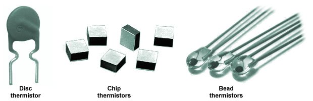
The main thermistor types
Thermistors must be supplied with electrical power in order to work, and this power will be converted to heat. This has the potential to raise the temperature of the thermistor and introduce errors into the temperature readings obtained. The degree to which a thermistor can dissipate power to its surroundings is called its dissipation constant, and will relate to the size of the thermistor (the smaller a thermistor element is, the more likely it is to experience self-heating). The problem can be mitigated by minimising the amount of current flowing through the thermistor and ensuring there is a good thermal pathway between the thermistor element and its surroundings.
The relatively small size of glass bead thermistors means that they respond very quickly to changes in temperature, but also limits their ability to dissipate power. Disc and chip thermistors tend to be larger, which means they do not respond to temperature changes as quickly as bead thermistors, but are better able to dissipate power.
Generally speaking, there is a trade-off between the degree to which a thermistor provides accurate results (referred to as its tolerance) and the speed with which it responds to changes in temperature. Modern disc and chip thermistors typically have an accuracy of between ± 0.1 °C and ± 0.2 °C for the temperature range 0 °C to 100 °C. Whilst it is possible to produce bead thermistors with comparable tolerances, their cost will be significantly higher.
Many industrial applications require temperature sensors that can function in a hostile environment. Although thermistor elements can be inserted directly into an operating environment, they are vulnerable to corrosion, oxidation and mechanical damage. Consequently, thermistor elements are often packaged inside a protective housing or probe, typically consisting of a closed-ended metal tube. The probe is usually packed with a thermally conducting material (e.g. epoxy resin) to ensure good thermal conduction between the thermistor element and the process being measured.
Advantages:
Disadvantages:
An infrared thermometer measures temperature without making direct contact with the object or substance to be measured by measuring the infrared radiation emitted by that object or substance. Infrared radiation (sometimes called blackbody radiation) is invisible radiant energy, first discovered in 1800 by the German-born British astronomer Frederick William Herschel (1738-1822). It is part of the electromagnetic spectrum, with wavelengths longer than those of visible light. Every form of matter with a temperature above absolute zero emits infrared radiation. The amount of infrared radiation emitted increases with temperature.
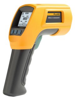
This high-temperature infrared thermometer can monitor temperatures of up to 900 °C
Herschel's discovery paved the way for a new kind of temperature measurement device that could be used at a distance from the target. Such devices eliminated the risk of damage or contamination due to contact with the target, and could safely be used to measure very high temperatures. Early infrared thermometers were heavy, bulky and difficult to operate. Their modern counterparts are typically lightweight hand-held devices that are easy to operate while at the same time offering a range of sophisticated features.
A typical infrared thermometer uses a lens to focus the received infrared light onto a detector, consisting of a thermopile (several serially-connected thermocouples - see above), that converts thermal energy into an electrical signal. The signal is then interpreted by an electronic circuit, which displays the temperature on an electronic display panel. Because the surfaces of different materials have different levels of emissivity, the instrument may need to be calibrated for use in a particular application. Reflective surfaces have a lower emissivity than non-reflective surfaces, and many infrared thermometers have an adjustable emissivity setting to take account of this.
The most commonly used type of infrared thermometer is a spot infrared thermometer which, as the name suggests, measures the temperature of a relatively small circular area on a surface. The actual size of the spot is determined by the distance-to-spot ratio (or D:S ratio) which is the ratio of the distance between the thermometer and the surface to be measured and the diameter of the spot. For a D:S ratio of 10:1, for example, the diameter of the spot will be one-tenth of the distance between the thermometer and the surface to be measured.
Most handheld devices have a fixed D:S ratio, which means that there is an optimal distance for temperature measurements. Accurate measurements can be obtained at other distances, but the size of the spot will vary accordingly. Care must be taken to ensure that the target completely fills the area covered by the spot. If not, infrared emissions from background objects may adversely affect the accuracy of the measurement. Many infrared thermometers are equipped with a laser pointer to make it easier for the user to centre the spot on the target area.
Infrared thermometers have many applications. They can be used to measure the temperature of objects affected by strong magnetic fields, or contained within a controlled, atmosphere, or subject to hazardous conditions. Fast response times mean they can be used to measure the temperature of moving objects (on a conveyor belt or assembly line, for example). They can also be used in high-temperature applications where the temperatures involved preclude the use of contact sensors, or in corrosive environments where contact sensors would be easily damaged, or to monitor surfaces that could become contaminated by contact with a physical sensor, or where the presence of a contact sensor could introduce a significant temperature gradient on the surface to be measured.
Infrared thermometers are typically used to monitor machinery and electrical equipment for hot spots, and to monitor temperatures in industrial processes. As well as handheld devices, infrared thermometers can be installed at fixed points in chemical and manufacturing plants to monitor temperature-critical operations. These devices are often controlled remotely using video monitoring equipment, and send their data to a control station. In the field of medicine, infrared thermometers may be used to measure the temperature of hospital patients without touching them (for example, under quarantine conditions). In recent years, airport workers have used infrared thermometers to screen passengers arriving from countries suffering from outbreaks of infectious diseases, such as the Ebola virus.
Advantages:
Disadvantages: