| Author: | |
| Website: | |
| Page title: | |
| URL: | |
| Published: | |
| Last revised: | |
| Accessed: |
Packet switching networks are digital networks in which Iarge blocks of data created by end-user processes can be broken down into smaller blocks of data called packets and sent from one network to another via routers. Networks that work in this way are called packet-switched networks. The concept of packet switching was developed in the early 1960s, and ARPANET was the world's first packet switching network (previously, communication networks used dedicated analogue circuits). Most WANs now use packet switching technologies such as X.25 and Frame Relay. In this type of network, there is no dedicated connection between two end systems, and the availability of different paths through the network eliminates dependence on any single network link. Furthermore, any link on the network can be used by any number of data packets, regardless of their source and destination, ensuring efficient use of network bandwidth.
Each packet has a header that contains the source and destination addresses, a sequence number that identifies the position of the packet in the original message, the length of the packets in bytes, and the total number of packets in the message. The routers on a packet switching network regularly exchange information about network topology, and the current state of the various network links. This information, together with the destination network address contained in the packet, enables the router to select the best route for an incoming packet. At the destination, the packets are reassembled into the original message. Armed with this information, a destination computer can request retransmission of missing packets because it can determine which packets have not been received.
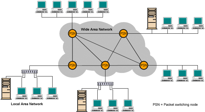
Packet switching nodes connect LANs in a wide area network
X.25 is a widely-used ITU-T protocol standard that specifies an interface between a host system and a packet-switched network. The standard specifies three layers of functionality that correspond to the bottom three layers of the OSI reference model. The physical layer is concerned with the physical interface between data terminating equipment (DTE), such as a host computer, and data circuit-terminating equipment (DCE), such as a modem, through which it is connected to a packet-switching exchange.
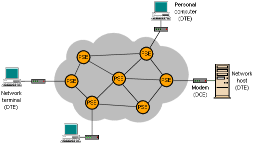
The relationship between devices in an X.25 network
The physical layer is often implemented using a standard known as X.21, but other standards, such as EIA-232, are also used. The data link layer provides reliable transfer of data over the physical link by transmitting the data as a sequence of frames. The data link layer standard used is link access protocol - balanced (LAP-B). The packet layer provides an external virtual-circuit service. User data is passed down to X.25 level 3, which appends control information in a header, creating a packet. The X.25 packet is then passed down to the LAP-B protocol, which appends its own control information in the form of both a header and a trailer, forming a LAP-B frame. The diagrams below show how data is encapsulated, and the relationship between the X.25 protocol layers and the OSI reference model.
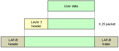
An X.25 packet encapsulates user data, and is encapsulated by a LAP-B frame
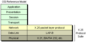
Relationship between X.25 protocol layers and the OSI reference model
X.25 can operate over either switched or permanent virtual circuits. In a switched virtual circuit, a call must be explicity set up before data can be transferred, and cleared once data transfer is complete. Data transfer takes place in the same way over permanant virtual circuits, but call setup and clearance is not required. A typical sequence of events for an X.25 session using a switched virtual circuit is illustrated below.
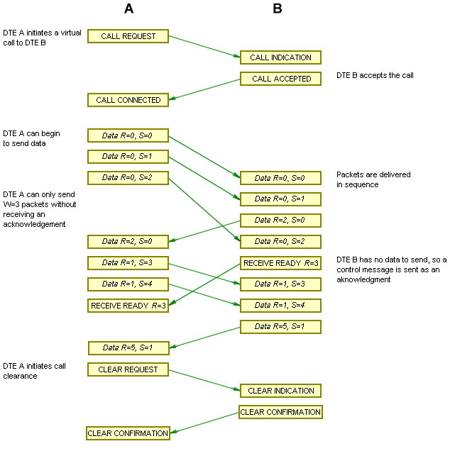
Sequence of events in an X.25 virtual call
In the sequence of events shown above, DTE A requests a virtual circuit to DTE B by sending a call request packet to its attached DCE. The packet includes the source and destination addresses, together with the virtual circuit number to be used for the new virtual circuit. The call request packet is routed through the packet switching network to the DCE attached to DTE B, which sends an incoming call packet to DTE B. This packet has the same format as the call request packet, but has a different virtual circuit number which is allocated by DTE B's attached DCE. DTE B accepts the call by sending a call accepted packet. DTEs A and B can then exchange data and control packets using their respective virtual circuit numbers.
As well as transmitting user data, X.25 needs to transmit control information in order to establish, maintain, and terminate virtual circuits. Various types of packet are used, but they all have (more or less) the same format. Each packet has a 24-bit or 32-bit header that includes a 12-bit virtual circuit number (expressed as a 4-bit group number and an 8-bit channel number. Some of the packet types are illustrated below.
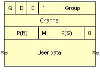
Data packet with 3-bit sequence numbers
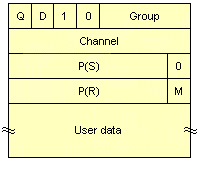
Data packet with 7-bit sequence numbers
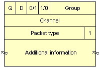
Control packet

RR,RNR and REJ packets with 3-bit sequence numbers
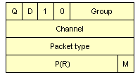
RR,RNR and REJ packets with 7-bit sequence numbers
A control packet will include a packet type field that identifies its control function, together with additional control information related to that function. The call request packet, for example, includes the following additions fields:
Details of the X.25 control packets are summarised below.
| DCE to DTE | DTE to DCE | VC | PVC |
|---|---|---|---|
| Incoming call | Call request | - | |
| Call connected | Call accepted | - | |
| Clear indication | Clear request | - | |
| DCE clear confirmation | DTE clear confirmation | - |
| DCE to DTE | DTE to DCE | VC | PVC |
|---|---|---|---|
| DCE data | DTE data | ||
| DCE interrupt | DTE interrupt |  | |
| DCE interrupt confirmation | DTE interrupt confirmation |  |
| DCE to DTE | DTE to DCE | VC | PVC |
|---|---|---|---|
| DCE RR | DTE RR |  | |
| DCE RNR | DTE RNR |  | |
| DTE REJ |  | ||
| Reset indication | Reset request | ||
| DCE reset confirmation | DTE reset confirmation |  |
| DCE to DTE | DTE to DCE | VC | PVC |
|---|---|---|---|
| Restart indication | Restart request | ||
| DCE restart confirmation | DTE restart confirmation |
| DCE to DTE | DTE to DCE | VC | PVC |
|---|---|---|---|
| Diagnostic |
| DCE to DTE | DTE to DCE | VC | PVC |
|---|---|---|---|
| Registration confirmation | Registration request |
A DTE can send an interrupt packet that bypasses the flow control procedures for data packets. The interrupt packet has a higher priority on the network than data packets. The reset packet facilitates error recovery by reinitialising a virtual circuit, in which case sequence numbers at both ends of the connection are reset to zero, and any data or interrupt packets in transit are lost. Resets can be triggered by conditions such as packet loss, sequencing errors, network congestion, or loss of an internal connection. More serious errors, such as a temporary loss of network access, are dealt with using a restart packet, which terminates all active virtual circuits. The diagnostic packet provides a means of flagging up errors that do not warrant reinitialisation, while the registration packet is used to invoke and confirm an X.25 facility.
A DTE can establish up to 4095 simultaneous virtual circuits with other DTEs using a single physical DTE-DCE link. The DTEcan assign these circuits internally to applications or processes in any way it pleases. The link between DTE and DCE provides full-duplex multiplexing. The 12-bit virtual circuit number within each packet identifies the virtual circuit to be used by that packet. Virtual circuit numbers are assigned according to a strict convention, with zero always being reserved for diagnostic packets common to all virtual circuits. Permanent virtual circuits are assigned numbers beginning with 1. Two other categories of numbers are set aside, one for one-way incoming virtual calls (assigned by the DCE using a previously unallocated number), and one for one-way outgoing virtual calls (assigned by the DTE, again using an unallocated number). The purpose of segregating the numbers in this way is to avoid the simultaneous selection of the same number for two different virtual circuits by the DTE and DCE. A fourth (two-way) virtual call category provides spare capacity that is shared by the DTE and DCE, to cover a possible overflow situation during peak traffic periods. This scheme is illustrated below
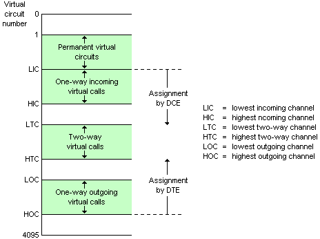
Virtual circuit number assignment
A sliding window is used for flow control. Each data packet includes a send sequence number, P(S), and a receive sequence number, P(R). By default, 3-bit sequence numbers are used, but a DTE may optionally request to use the extended 7-bit sequence numbers via the user facility mechanism. For 3-bit sequence numbers, the third and fourth bit of all data and control packets are 0 and 1 respectively. For 7-bit sequence numbers, the bits are 1 and 0. The P(S) of each new outgoing data packet on a virtual circuit is one greater than that of the preceding packet, modulo 8 or modulo 128 (depending on whether 3-bit or 7-bit sequence numbers are used). P(R) is set to the sequence number of the next packet expected from the other end of the virtual circuit, allowing acknowledgments to be "piggy-backed" on outgoing data frames. If one side has no data to send, it can acknowledge incoming packets with either a receive ready (RR) or a receive not ready (RNR) control packet. The default window size is 2, but may be set as high as 7 for 3-bit sequence numbers, or 127 for 7-bit sequence numbers.
An acknowledgement may have either local or end-to-end significance, depending on whether or not the D-bit is set. By default, D = 0, and the acknowledgement is exercised between the DTE and the network. It is used by the local DCE (or the network) to acknowledge receipt of packets and implement flow control between the DTE and the network. If D = 1, the acknowledgment is from the remote DTE. Error control is based on the go-back-N ARQ (automatic repeat request) data link error control mechanism, in which the destination station will send a negative acknowledgement (NAK) if it detects an error in a frame, and will discard the frame and all subsequent frames until the eroneous frame is received without errors. A source station receiving a negative acknowledgement must retransmit the offending frame and any other frames subsequently transmitted. In X.25, a negative acknowledgement takes the form of a reject control packet (REJ).