| Author: | |
| Website: | |
| Page title: | |
| URL: | |
| Published: | |
| Last revised: | |
| Accessed: |
The display adapter in a computer system (often called a graphics card) is the hardware responsible for generating the images that appear on the system's visual display unit. In the first IBM personal computers the display adapter took the form of an expansion card that was mounted in one of the Industry Standard Architecture (ISA) slots on the system motherboard. It used the Monochrome Display Adapter (MDA) standard introduced by IBM in 1981, and was only capable of displaying text at a screen resolution of 720 x 350 pixels.
Modern display adapters can take the form of a separate card or may be integrated into the motherboard. They are capable of operating at very high resolutions and displaying millions of colours. Even relatively modest display adapters can now handle computer animations, video playback, and 3D interactive games. Indeed, it is probably the computer gaming industry that has been the main driver behind the development of high-performance display adapter technology. Other important drivers include the almost universal adoption of the graphical user interface (GUI), a phenomenal growth in the number of multimedia applications, and the popularity of Internet streaming media.
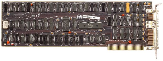
An MDA video card
Displaying high resolution images and millions of colours demands a considerable amount of both processing power and computer memory, due to the enormous amount of information that must be processed. Even a relatively modest screen resolution (by today's standards) of 1024 x 768 pixels gives a total of 786,432 pixels. If a colour depth of 32 bits per pixel is required, the amount of memory required to store a single screen of information (referred to as a frame) is 786,432 x 32 = 25,165,824 bits of data, or 3 megabytes.
The number of calculations that must be performed when rendering 3D scenes for many computer games would severely tax the capabilities of the computer's main processor. In order to run state-of-the-art computer games and other computationally intensive graphical applications such as flight simulators and virtual medical training environments, a powerful graphics adapter is required. This will invariably be an add-on card with its own graphical processing unit (GPU), and anything up to four gigabytes of dedicated memory. These high-end display adapters have a tendency to be bulky, consume a lot of power, and require their own cooling system.
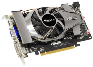
An Asus ATI EAH5750 FORMULA PCI-E display adapter
The display adapter shown above is one of the mid-range products currently available and has a price tag somewhere between £100 and £160. It has a gigabyte of RAM, and can produce output in a range of signal formats including VGA (at a maximum resolution of 2048 x 1536 pixels), DVI (at a maximum resolution of 2560 x 1600 pixels) and HDMI (the various video standards and output formats will be described later on this page).
When considering the purchase of a graphics card suitable for gaming or other graphically intensive applications, you will also need to take several other factors into account. The system motherboard must have an appropriate expansion slot for the card (usually a PCI Express slot), and you should check that there is enough space inside the case to physically accommodate the new card. Make sure that the power supply has both sufficient capacity and the right number and type of cable connections required. Operating system compatibility may also be an issue, since many cards require a minimum version number of DirectX in order to function correctly (DirectX is a collection of application programming interfaces (APIs) used in the programming of games and other graphics-intensive applications).
The specifications for the Asus EAH5750 illustrated above state that a 500W or greater power supply is needed, with two 6-pin PCI-E power connectors. The host operating system should support DirectX 11, which effectively means the system must be running Windows Vista or above.
A display adapter built into the motherboard (often referred to as a graphics controller) usually has a small amount of RAM that is augmented with some of the system RAM (the RAM "borrowed" from the system becomes unavailable for use by the system). This on-board graphics capability is invariably incapable of coping with the demands of sophisticated 3D computer games, but is perfectly adequate for office type applications, surfing the web, and most business software.
The majority of new computers have an on-board display adapter, although the on-board graphics can be disabled if a dedicated graphics card is installed, either by the user explicitly disabling the on-board controller in BIOS or automatically when the system detects the presence of an additional graphics card. Note that for small form factor computers it may be necessary to source a suitable card from the manufacturer of the system, assuming one is available. For laptop and netbook computers, upgrading the display adapter is not usually an option.
The images you see on your computer monitor are created using millions of tiny dots called pixels, arranged in rows and columns on the screen. Information about each pixel to be displayed is stored in video memory. This information is read by the display adapter and converted into a signal that the monitor hardware can use to display the pixel. The colour of each pixel is determined by the intensity of three primary colours - red, green and blue.
The signal sent to the monitor must tell it how much red, green and blue output to produce for each pixel. These red, green and blue values are often referred to as RGB values. The total number of pixels that make up the image will depend on the width of the image in pixels (its horizontal resolution) and height of the image in pixels (its vertical resolution), and can be calculated by multiplying these values together. Thus the total number of pixels for a screen resolution of 640 x 480 pixels is equal to 640 x 480 = 307,200.
Screen resolution is important because it determines the amount of detail that can be shown in an image. The greater the number of pixels displayed, the more information can be conveyed to the user. In the very low resolutions used on early computer systems, it was possible to pick out individual pixels on the screen quite easily. With today's high resolution displays this is rarely possible.
The left hand image below is 320 pixels wide by 200 pixels high, which was the highest colour graphics resolution available for the IBM PC in 1981 (note that neither of the images shown could have been displayed on a CGA monitor, as the CGA display adapter could only display four colours). The right hand image is a small section of the first image magnified eight times. You can clearly see the individual pixels that make up the image.
The physical size of the display screen has changed little in real terms. The original IBM 5153 CGA colour monitor had a 12 inch screen as opposed to the 15 - 19 inch screens in widespread use today. In contrast, display resolutions now have several times as many pixels in both the horizontal and vertical dimensions. The trend has therefore been for pixel density to increase, giving sharper and more detailed images. There is of course a cost, as the amount of memory required to store the image data has increase dramatically.
 |
 |
A 320 x 200 pixel image (left) and a close-up view (right) |
|
The number of pixels alone is not the only factor that determines how much memory is required to store a single screen image. For a simple monochrome image in which each pixel is either black or white (or, as in early monochrome displays, amber or green), only one bit is required to store information about a single pixel, since it is either illuminated or dark, on or off.
The number of bits required to store information about the colours used in a particular image is known as its colour depth, expressed as bits per pixel. The very first display adapters capable of displaying colour graphics were limited to a fixed palette of four colours. The colour to be displayed could be determined using just two bits, which allowed four distinct colour values (0 to 3). The number of colours available soon rose to sixteen, requiring four bits of data for each pixel.
When the number of bits per pixel rose to eight a total of 256 colours became available, allowing reasonably good quality images to be displayed. Obviously the amount of memory required to store an image at a colour depth of 8 bits per pixel is far greater (eight times as much, in fact) than the amount required for a monochrome image.
The number of bits per pixel quickly doubled to sixteen, allowing a total of 65,536 separate colours to be displayed on the screen (216 = 65,536). When a further eight bits were added, giving a colour depth of 24 bits per pixel, a staggering 16,777,216 (224) separate colours were available. This is far greater than the total number of pixels that can actually be displayed by any computer monitor currently available.
Because of the way that video memory is accessed in most cases, the number of bits used to store information about a single pixel is actually 32, and most operating systems and applications refer to a 32-bit colour depth. The amount of memory required to store a single screen image in bytes is calculated as follows:
Memory (in bytes) = width (in pixels) x height (in pixels) x bits per pixel ÷ 8
So, for a 32 bit image with a resolution of 1024 x 768 pixels, the calculation would be:
Memory = 1024 x 768 x 32 ÷ 8 = 3,145,728 bytes (or 3 megabytes)
As mentioned earlier, the colour displayed on screen for a given pixel depends on the intensity of the three primary colours - red, green and blue. For a colour depth of 24 bits per pixel, the intensity of each colour is stored as 8 bits of information, giving a total of 256 possible intensity values for each of the three primary colours. This yields a total number of colour permutations of 16,777,216 (256 x 256 x 256).
For a colour depth of 16 bits per pixel, the numbers don't break down so neatly. A compromise solution is used in which 5 bits are used for each of the red and blue colour components (32 possible intensities), and 6 bits for green (64 possible intensities). The total number of colour permutations here is 65,536 (32 x 32 x 64). Many people find it difficult to tell the difference between 16-bit and 24-bit colour images, and for most business applications a colour depth of 16 bits per pixel is perfectly adequate. The same image is displayed below at various colour depths.

24 bits per pixel (17,639 colours used)

8 bits per pixel (245 colours used)

4 bits per pixel (16 colours used)
1 bit per pixel (2 colours used)
Of the above images, only at very low colour depth (4 bits and 1 bit per pixel) is there an obvious degradation in quality, although closer inspection of the 8 bits per pixel version will also reveal some shortcomings. Even so, a reasonable image quality is achieved at 8 bits per pixel.
In practice, although some applications can take control of the screen and change the colour depth used for displaying the screen images they produce (some games for example), the operating system will determine the colour depth used by the display adapter. By default, the operating system normally selects the highest colour depth available (usually 32 bits per pixel) in order to ensure the best quality display possible, although the user may select a different colour depth if they wish.
You may note from the images shown above that even using only 16 colours, the image manages to achieve a reasonable approximation to the 24-bit version. This would not be the case if the 16 colours available were restricted to only those present in the 16-colour palettes provided by the CGA and EGA display adapters (see below) used on early IBM personal computers.
In fact, the sixteen colours in the palette can be chosen from the entire range of 16,777,216 colours, because the intensities of each of the RGB values used for the colours in the palette are stored using 8 bits. The 4 bits of information stored for each pixel in the screen image is essentially an index number that indicates which of the sixteen colours is to be used for that pixel.
The area of video memory used to store the pixel information for a single screen image is called the frame buffer, and as we have seen its size will depend on the resolution and colour depth used. The area of conventional memory reserved for video RAM is simply too small to hold a screen image for high resolution 32-bit images, so virtually all modern graphics cards come with their own video memory.
Most on-board graphics controllers are capable of handling the requirements of 2D applications, although they usually "borrow" some of the system's main memory in order to store image data, as well as the results of any image processing operations they may undertake. Display adapters capable of running today's 3D interactive games need large amounts of memory, both for storing screen images and for storing the results of the large number of calculations required for creating each new image. The memory used is often faster than standard system memory, and we will be looking at the development of video RAM later on this page.
As mentioned above, the first IBM PC had an MDA display adapter that could only display monochrome text. The output consisted of 80 columns x 25 rows of characters, with each character having on-screen dimensions of 9 pixels wide x 14 pixels high. From this information, it is possible to infer a screen resolution of 720 x 350 pixels (an aspect ratio of 72:35) and a colour depth of one bit per pixel. It should be noted however that individual pixels could not be directly manipulated.
The MDA card had 4 kilobytes of video RAM on board, and a screen refresh rate of 50 Hz (i.e. the contents of the screen were redrawn by the display hardware fifty times every second). The characters displayed were taken from the 256-character IBM character set which was stored in the display adapter's read-only memory (ROM). It was however possible to display graphics of a sort and even to create rudimentary PC games through the imaginative use of some of the more exotic characters in the IBM character set.
The illustration below shows the title screen of a very early Microsoft game designed for use with the MDA display adapter. The IBM logo appears to have been created by repeatedly displaying an IBM block character at the requisite screen coordinates.
The title screen for an early Microsoft game designed for an MDA display
The adapter itself was equipped with 4 kilobytes of memory, and utilised a dedicated area of the main system memory (known as video RAM) starting at memory address B000:0000. Each screen character was stored in memory as a two-byte word (a word is the amount of data that can be stored by a processor's registers, in this case 16 bits). One byte contained the character code, while the other contained the attribute (e.g. high intensity, underlined, blinking etc.)
The contents of the screen were effectively held in a two-dimensional array of words in which each array element corresponded to a particular 9 x 14 pixel matrix at a specific character position on the screen. The display adapter would read the contents of the video RAM many times per second to determine what character elements to display at each character position. Changing the value of a particular array element in memory resulted in a change in the character displayed at the corresponding screen coordinates (this is referred to as memory mapped I/O).
1981 also saw the arrival of IBM's Colour Graphics Adapter (CGA), which featured 16 kilobytes of on-board video RAM. The CGA card occupied an ISA slot on the system's motherboard. It had a screen refresh rate of 60 Hz, utilised system memory starting at address B800:0000, and supported several distinct modes of operation. The highest resolution graphics mode that could be achieved was a 640 x 200 pixel monochrome display. This is a lower screen resolution than MDA's 720 x 350 monochrome display, although individual pixels could be manipulated programmatically.
Using the same resolution, CGA could display 80 columns x 25 rows of characters in 16 colours (requiring a colour depth of 4 bits per pixel), although the use of an 8 x 8 pixel matrix for each character resulted in text of significantly poorer quality that that produced by an MDA card. Like MDA, the CGA card featured a 9-pin D-sub (DE-9) connector. It could be connected to a television, or to a dedicated monitor capable of displaying colour in order to take advantage of the colour output. Note however that IBM did not actually produce a colour monitor until 1983, when they introduced the 5153 Personal Computer Color Display.
As with MDA, rudimentary graphics could be displayed at the 640 x 200 (or lower) resolution by clever use of graphical characters, enabling all 16 colours in the CGA palette to be used. The colours in the CGA pallet were determined according to the RGBI colour model, in which the first three bits represent the presence (bit is set) or absence (bit is not set) of the red, green and blue colour components respectively, while the fourth bit increases the intensity of all three colour components if set (if a bit is set, it has a value of 1, otherwise it has a value of zero).
The highest resolution colour graphics mode achievable was 320 x 200 pixels. In this mode, every pixel could be manipulated programmatically. The display was limited to just four of the 16 CGA colours, although two standard palettes were available in which the background colour could be any one of the 16 CGA colours (the default background colour in both cases was black). The CGA colour palettes are illustrated below.
The CGA colour palettes
The high-intensity version of Palette 0 or Palette 1 can be accessed by the program setting the high-intensity bit. A third 4-colour palette consisting of cyan, red and white plus the background colour can be used if the composite colour burst bit is disabled by the program, although it is not officially documented by IBM and can only be seen on RGB monitors.
Many games were written using this palette because it was felt to be more attractive than the official palette options. Additional colours could be approximated using dithering (placing pixels of a different colour next to one another to create the appearance of a third colour) although at such low resolutions it was fairly easy to pick out the colour of individual pixels. The images below are screenshots from early PC games running on a CGA display adapter. The first image demonstrates the use of dithering.
IBM's Castle Master, circa 1990 (Palette 0)
IBM's Alley Cat, circa 1983 (Palette 1, high intensity)
Like MDA, CGA used the character set stored in its onboard ROM when in text mode. The MDA cards were the popular choice for business use however, because the displayed text was of a much better quality than that produced by CGA cards, and the display monitors required to take full advantage of the capabilities of a CGA card were quite costly. As an added bonus, IBM's initial MDA offering included a parallel printer port in addition to the DE-9 connector.
Ironically the arrival of the Enhanced Graphics Adapter (EGA) standard in 1984 actually increased the popularity of CGA cards, because their price fell significantly. As a result, PCs at the lower end of the market produced by both IBM and their competitors tended to be equipped with CGA display adapters.
Up until 1987, many computer games were still being written for entry level computers that featured a CGA card. 1987 saw the introduction of the new Video Graphics Array (VGA) standard, effectively making EGA the new entry-level display standard.
EGA was introduced by IBM in 1984 for its new PC-AT model personal computer. Like its predecessors it was mounted in an ISA slot, featured a DE-9 connector, and had a screen refresh rate of 60 Hz. It also displayed 80 columns x 25 rows of characters in text mode, but the maximum resolution was increased to 640 x 350 pixels (an aspect ratio of 64:35) and more colours were available.
EGA cards initially included 64 kilobytes of on-board RAM, but this was increased to 256 kilobytes in later versions. A 16 kilobyte ROM chip provided additional graphics functions not found in the system BIOS. In text mode, EGA used the same area of memory (starting at address B800:0000) as EGA, but for its standard graphics modes it used memory starting at address A000:0000. Up to sixteen colours could be displayed at the same time, a colour-depth of 4 bits per pixel.
Note however that the colours displayed could be selected from a standard palette of 64 colours, which utilised two bits per pixel for each of the red, green and blue colour components. This allows one of four values (0, 1, 2 or 3) to be selected for each of the red, green and blue pixel elements. The 64-colour EGA palette is illustrated below, together with the default 16-colour palette. Note that the colours have been identified using their equivalent hexadecimal RGB values. Note also that the default palette has the same colours as the 16-colour CGA palette.
The EGA 64-colour palette and default 16-colour palette
The two-bit binary colour values for each of the red, green and blue pixel components defined the intensity of each colour for a given pixel. A value of zero indicates that the colour is turned off. A value of 1 represents one-third intensity, 2 represents two-thirds intensity, and 3 indicates full intensity.
EGA cards could emulate both the original CGA graphics modes and 16-colour versions of the 640 x 200 and 320 x 200 CGA graphics modes (these were limited to the 16 colours in the CGA RGBI palette). They could also work with an MDA monitor if the switches on the card were set up correctly, and were able to operate in both the 640 x 350 MDA monochrome graphics and standard MDA text modes.
EGA was superseded in 1987 by the Video Graphics Array (VGA) standard, introduced by IBM with the new PS/2 model personal computer. It was to become the last widely accepted display adapter standard. Virtually every display adapter produced since 1987 can trace its origins back to VGA, and most graphics cards support one or more of the original VGA modes.
VGA is probably most closely associated with its 640 x 480 pixel graphics resolution, in which it can display 16 colours (a colour depth of 4 bits per pixel). This resolution gives an aspect ratio of 4:3 which has become the standard aspect ratio for PC screen displays. At a resolution of 320 x 200 pixels, VGA can display 256 colours (a colour depth of 8 bits per pixel). All of the colours in the VGA palette can be selected from a much larger palette in which each colour component is represented using 6 bits, allowing 64 possible values for each of the red, green and blue components of a pixel (64 x 64 x 64 = 262,144).
A text mode with a screen resolution of 720 x 400 pixels was available, allowing 80 columns and 25 rows of text utilising a character matrix of 9 x 16 pixels. Text could be displayed with a choice of 8 background colours and 16 foreground colours. VGA could potentially achieve a maximum resolution of 800 x 600 pixels, and a highest screen refresh rate of 70 Hz (the standard refresh rate for the 640 x 480 pixel graphics mode was 60 Hz).
IBM's PS/2 computer, circa 1987
VGA differed in several ways from its predecessors. One major change was that the signals sent to the monitor were analogue rather than digital, allowing for a more accurate representation of colour (this of course meant that older monitors that relied on transistor-transistor logic (TTL) signalling would not work with VGA). Output was via a 15-pin mini-D connector (see below) that became known as the VGA connector, still the most commonly used connector type for computer display equipment despite the emergence of several other types in recent years.
Another innovation was the use of a single application-specific integrated circuit (ASIC) that replaced most of the discrete logic chips found on the MDA, CGA and EGA cards. This not only drastically reduced the overall size of the printed circuit board required for later add-on cards, but also allowed the display adapter to be located on the PC's motherboard providing it was accompanied by the other components necessary for it to function. These included timing, video memory (of which 256 kilobytes was required to implement the full functionality of VGA) and RAMDAC chips (RAMDAC will be discussed later on this page). IBM's first PS/2 PCs were provided with an onboard VGA display adapter.
The DE-15 VGA 15-pin connector socket
VGA can emulate many of the display modes of EGA, CGA and MDA with the additional benefit that although the CGA and EGA modes were still limited as to the number of colours they could display, those colours could be selected from the much larger range of colours available to VGA. Furthermore, VGA used different areas of video RAM (the address space ranging from A000:0000 to B000:FFFF), depending on the mode selected. By default, VGA used a 64 kilobyte segment starting at address A000:0000 for both VGA and EGA-compatible graphics modes, a 32 kilobyte area starting at B000:0000 for monochrome text mode, and a second 32 kilobyte area starting at address B0000:8000 for colour text mode and CGA-compatible graphics mode.
The use of separate memory areas for different display modes made it possible for two monitors to be connected to a single personal computer with both an MDA card and a VGA card (or EGA or CGA card) installed. In the early 1980s this arrangement was typically used to display text-based information (spreadsheet data, for example) on an MDA display while viewing related graphical information (such as charts and graphs) on a second, low-resolution CGA display.
A number of other display standards emerged during the 1980s, including the Hercules Graphics Card (HGC) which was a popular alternative to IBM's MDA technology and achieved a resolution of 720 x 348 pixels. As well as the standard text modes, the HCG was capable of displaying monochrome graphics - something the MDA display was not able to do.
Software packages like the popular Lotus 1-2-3 spreadsheet program provided support for the HGC, which as a consequence could display graphs and charts generated by the program as well as standard text-based spreadsheet information. IBM was the dominant force throughout most of the 1980s however, producing new standards such as 8514/A and MCGA, both of which were released in 1987 (the same year as VGA).
The 8514/A display adapter provided a higher resolution colour graphics mode (1024 x 768 pixels) with a colour depth of 8 bits per pixel, allowing 256 separate colours to be displayed at the same time. This higher resolution only worked on interlaced monitors at a screen refresh rate of 43.5 Hz, however. An interlaced monitor displays alternate lines on each refresh cycle in order to make more efficient use of bandwidth.
The interlaced monitors proved unpopular because they tended to produce flicker, and even at higher frequencies could cause eye strain after prolonged use. Nevertheless, the 8514/A display adapter was the first mass-produced display card to feature hardware acceleration (see below), albeit of a somewhat limited nature. This meant that it could undertake some of the display-related tasks normally carried out by the CPU. It was also the forerunner to IBM's Extended Graphics Array (XGA).
The Multicolor Graphics Adapter (MCGA) was offered by IBM as a cheaper alternative to VGA on some of its PS/2 model personal computers. While capable of 256 colour graphics at a resolution of 320 x 200 pixels, MCGA's 640 x 480 resolution was restricted to a monochrome display only.
Later PS/2 model computers featured IBM's XGA display adapter, first introduced in 1990. Like the 8514/A standard, XGA featured hardware acceleration. The initial version provided resolutions of 640 x 480 and 800 x 600 pixels at a colour depth of 16 bits per pixel, allowing 65,536 separate colours to be displayed (this colour depth was referred to as high colour).
XGA also supported a resolution of 1024 x 768 pixels with a colour depth of 8 bits per pixel (256 colours). XGA-2 increased the colour depth for the 1024 x 768 resolution to 16 bits per pixel (high colour), and added support for a 640 x 480 resolution that could display 16,777,216 colours, a colour depth of 24 bits per pixel (referred to as true colour).
From the end of the 1980s onwards, IBM faced increasing competition from its competitors in the race to develop bigger and better display adapters, and effectively relinquished its role of defining video display standards. A new generation of graphics cards emerged that were loosely described as Super VGA (SVGA), a label effectively applied to a whole range of proprietary technologies that extended the capabilities of VGA.
There was no real consensus among different manufacturers about what actually constituted SVGA, resulting in the proliferation of multiple standards, chipsets, resolutions, colour depths and refresh rates. As a direct result of this, virtually every new display adapter produced required its own driver software to enable it to work with the computer's operating system. Fortunately, most of these new products could also operate in standard VGA mode.
In an attempt to rationalise computer video graphics standards a number of manufacturers, led by the Japanese IT company NEC, established the Video Electronics Standards Association (VESA) in 1989. The initial aim was to create a standard for 800 x 600 pixel SVGA display adapters. VESA has subsequently issued a number of graphics-related standards, and is still active in the development of new standards, although the organisation has been heavily criticised for a failure to disclose information about some older standards, and for levying hefty charges to non-members for documentation relating to new standards (many other related industry standards bodies make their standards documentation freely available for download).
The VESA standard pertaining to SVGA is called the VESA BIOS Extension (VBE), and is a largely successful attempt to establish a standardised application programming interface (API) between application software and the display adapter. The most recent version of VBE is version 2.0. Graphics cards that support the VESA SVGA standards (either directly in hardware or via driver software) allow programmers to take advantage of the standard API without having to write device-specific program code.
Since the arrival of SVGA at the end of the 1980s there have been a number of new display adapter standards, many based on IBM's XGA standard, that reflect the increasing demand for high resolution computer graphics and an ever more diverse range of user applications. The 4:3 and (to a lesser extent) 5:4 aspect ratios that were ubiquitous prior to about 2003 have in many instances been displaced by widescreen formats on both laptop computers and standalone LCD monitors. These widescreen formats are popular for a number of reasons, including the ability to display two pages of a document side by side on the screen, and for viewing widescreen movies.
Some of the more significant standards are described in the table below (note that all of these standards support a colour depth of 32 bits per pixel). The following illustration gives an idea of how display resolutions have evolved.
The evolution of personal computer display resolutions
| Standard | Description |
|---|---|
| WXGA | Widescreen Extended Graphics Array - an extension of XGA found on some recent laptop computers that provides pixel resolutions of 1280 x 800, 1366 x 768, and 1300 x 768. Note that the first two resolutions give aspect ratios of 16:10 and 16:9 respectively. The third resolution is a slightly narrower aspect ratio also found on some 26" LCD television screens. |
| SXGA | Super XGA - sometimes referred to as Extended VGA (XVGA). SXGA has a resolution of 1280 x 1024 and an aspect ratio of 5:4, the native resolution and aspect ratio for many 17" and 19" LCD monitors. |
| SXGA+ | Super XGA Plus - most often found on 14" and 15" notebook computers, SXGA has a resolution of 1400 x 1050 (an aspect ratio of 4:3). |
| WXGA+ | (or WSXGA) Widescreen Extended Graphics Array Plus - a non-standard set of display resolutions that usually refers to a resolution of 1440 x 900 (an aspect ratio of 16:10) found in notebook computers and many 19" widescreen LCD monitors. |
| UXGA | Ultra XGA - this standard has a resolution of 1600 x 1200 (an aspect ratio of 4:3), the native resolution for many 20" and 23" LCD monitors. |
| WSXGA | Widescreen SXGA - at 1680 x 1050 (an aspect ratio of 16:10), WSXGA provides the native resolution for many 22" monitors. |
| WUXGA | Widescreen UXGA - this standard has a resolution of 1920 x 1200 (an aspect ratio of 16:10) found in a number of high-end notebook computers and many 23" - 27" widescreen LCD monitors. |
| QWXGA | Quad Wide Extended Graphics Array - both Samsung and Dell have produced 23" LCD monitors that support QWXGA's 2048 x 1152 resolution (an aspect ratio of 16:9). |
| WQXGA | Widescreen Quad Extended Graphics Array - at 2560 x 1600 (an aspect ratio of 16:10), this is the native resolution for a number of 30" widescreen LCD monitors. |
The graphics processing unit (GPU) is a dedicated microprocessor that performs most of the calculations required for drawing images on the screen. In the early days of personal computers, these calculations were carried out by the computer's central processing unit (CPU) and the results were used to send image data to the frame buffer.
The main task of the display adapter hardware was to translate the information in the frame buffer into a signal that the monitor could understand and display as an image on the screen. While this worked well for command line operating systems like DOS and low resolution graphic modes that were limited to only a few colours, the advent of higher resolutions and colour depths together with operating systems and applications that featured graphical user interfaces (GUIs) meant that the resources of the CPU were being severely stretched.
In response, manufacturers of display adapter hardware began to produce cards that included specialised hardware designed to take over some of the processing involved in producing image data. Such cards were known by the generic term accelerators, because they could carry out the required tasks more quickly than the processor. Instead of making all of the necessary calculations required to draw a window on screen, for example, the CPU could simply send a basic specification for the window to the graphics card, and the on-board acceleration hardware would perform the necessary calculations. The CPU was thus able to carry out its other tasks more efficiently.
Today, the display adapter has its own processor that is dedicated to carrying out the enormous number of floating-point calculations necessary to render high definition 2D and 3D graphics. The GPU on a modern graphics card must carry out a huge number of calculations in order to translate the three-dimensional image data typically generated by gaming software and other 3D applications into a two-dimensional image that can be displayed on the screen. Due to the dynamic nature of such software, a large number of different images must be displayed on the screen every second to create an effective 3D experience for the user. Most GPUs are today manufactured by ATI Technologies (now a subsidiary of AMD) or NVIDIA.
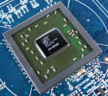
The ATI Cedar GPU in a Radeon HD5450 graphics card
The ATI Cedar GPU (illustrated above) is one of the less powerful graphics processors in the ATI Evergreen family of GPUs first introduced in 2009. It is seen here in the ATI Radeon HD 5450 graphics card, which is relatively inexpensive at around £40. Nevertheless, it is probably twice as fast as any comparable integrated GPU, and while probably not suitable for running state of the art computer games can carry out 104 billion floating point operations per second. The Radeon HD 5450 graphics card will happily support up to three monitor displays simultaneously.
GPUs today are highly parallel, with literally hundreds of arithmetic and logic units (ALUs) and floating point units (FPUs). The need for this degree of parallelism is due to the literally hundreds or thousands of polygons that make up a typical three dimensional scene in a modern computer game or simulation. The GPU must be able to perform calculations to determine whether each polygon is visible or not in a screen image. It needs to process the x, y and z coordinates of each of the polygon's vertices and convert them to x and y coordinates for a two-dimensional image. It also needs to determine the colour of each pixel to be drawn to create the impression of a solid surface for the polygon. In a dynamic 3D environment, this rendering process must be repeated many times per second.
The main difference between a GPU and a conventional CPU is that the GPU is essentially carrying out the same, limited number of operations on large numbers of different data streams (or pipelines) simultaneously. The speed at which the GPU can achieve this stream processing is determined by the number of pipelines available (which in turn is dependent on the number of floating point units present), the speed of the GPUs clock, and the speed with which data can be transferred between the GPU and the display adapter's video memory (this is normally many times faster than between the CPU and main system memory).
The GPU will also often include hardware that can perform video decoding functions, facilitating the playback of DVD or even Blu-ray content, and the display of streaming video media. New technologies currently available for increasing the processing power available for graphic displays include NVIDIA's Scalable Link Interface (SLI) and ATI's Crossfire, both of which allow multiple GPUs to be used to process a single image.
Although lacking the broad range of functionality characteristic of a conventional CPU, GPUs can perform floating point operations many times faster, and their stream processing capabilities enable them to simultaneously execute large numbers of small programs. For this reason, GPUs are becoming increasingly widely used in computer systems handling large-scale simulations, including a number of supercomputing applications.
The increase in the computational power of the display adapter has been matched by an increase in power consumption. This essentially means that more heat will be produced by the display adapter, in particular by the GPU or video memory. Many high-end graphics cards of the type used for serious computer gaming now require their own cooling systems.
As a minimum requirement, most cards will include a heat sink made of a heat-conducting metal that transfers heat away from the core components. In many cases, a fan is required to maintain a sufficient flow of air over the heat sink. In some systems, a heat sink is used that consists of a hollow chamber through which water is pumped in order to transfer heat away from the GPU. The use of a heat sink alone is referred to as passive cooling, and may well be sufficient for most integrated graphic controller chips.
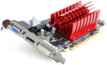
A heat sink provides passive cooling a Radeon HD5450 graphics card
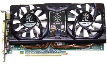
A water-cooled NVIDIA GeForce 9800 GT graphics card
By the year 2000, nearly twenty years after the IBM PC first appeared, a typical high-end display adapter had in the order of 128 megabytes of video memory. By 2005, the first PCI Express graphics cards with 512 megabytes of video memory had appeared. The amount of video memory available is important because it determines how much information the graphics card can store about the images it is required to display.
The type of memory used for display adapters was originally the same Dynamic Ram (DRAM) as that used for the main system memory, but the increasing demands of computer games and other graphically intensive applications required a kind of memory that could be accessed much more quickly due to the amount of data used for each screen image and the large number of frames displayed per second.
During the late 1980s and early 1990s, the type of memory most commonly used for the image frame buffer was a dual-ported type of DRAM called Video RAM (VRAM). Dual-ported memory allows read and write operations to occur simultaneously, speeding up overall access times.
DRAM stores each bit in memory as a charge stored on a microscopically small capacitor. Because this charge leaks away very quickly, the contents of memory need to be refreshed after each read or write operation. During the refresh cycle, no data can be read from or written to memory. Data words (a word is the amount of data that can be held in a processor register - typically two, four or eight bytes) are stored in rows and columns in memory. DRAM reads an entire row in a single read operation, and discards everything except the data word located at the memory address specified for the read.
VRAM gets around the limitations of DRAM in two ways. First, it moves all of the data words read in a single read operation into a separate row buffer so that those bits can be accessed serially by the display circuitry, greatly reducing the overall number of read operations required. Second, it has two input-output ports to allow data to be written to memory by the processor at the same time that it is being read by the display circuitry. VRAM was more expensive than DRAM, but less so than previous forms of dual-ported memory, making high-resolution, high speed colour graphics economically viable. VRAM was eventually superseded by synchronous DRAM (SDRAM) technologies in the late 1990s.
A number of different memory types have been used with display adapters since the 1990s. SDRAM is synchronised with the system bus, allowing the pipelining of instructions not possible with standard (asynchronous) DRAM, and improving memory access times. From 2003 onwards however, the trend has been towards some form of double data rate synchronous dynamic random access memory (DDR SDRAM), first introduced in 2002. As the name suggests, this type of memory doubles the data rate by transferring data on both the rising and falling edge of the clock signal generated by the memory bus clock.
DDR SDRAM has a 64-bit wide data bus width, so for the maximum clock frequency of 200 MHz (and ignoring some non-standard manufacturer optimisations that achieved higher speeds) the data rate would be 200 x 2 x 64 = 25,600 megabits per second (3200 megabytes per second, assuming metric units are used). Bear in mind that this is the maximum data rate that can be achieved between the GPU and the video memory on the graphics card itself.
DDR2 SDRAM was introduced in 2003 and doubled the width of the memory data bus to 128 bits. The DDR2 specification also increased memory bus speeds (up to a maximum of 533 MHz) but reduced the internal clock speed to half that of the memory bus, increasing data rates while achieving lower power consumption. Data is transferred at a rate of 128 bits for each half-cycle of the internal clock, so for a bus frequency of 400 MHz, the maximum data rate would be 6400 megabytes per second (128 x 2 x 400 x 0.5 / 8 = 6400).
2003 also saw the introduction of the new Graphics DRAM 3 (GDDR3) memory standard for video memory developed jointly by ATI and the Joint Electron Devices Engineering Council (JEDEC). Based on DDR2 SDRAM, GDDR3 achieves a reduced power consumption that allows higher bus speeds and reduces the complexity of cooling systems.
The successor to GDDR3 was GDDR4 but adoption of this technology has not been widespread. Many current display adapters still use GDDR3, with some graphics vendors opting for DDR3 SDRAM (the successor to DDR2 SDRAM) which increases maximum bus speed to 1066 MHz, twice that of DDR2. The latest video RAM technology is GDDR5, which is based on DDR3 and provides significant improvements in bandwidth over GDDR3. The first products to use GDDR5 was ATI's Radeon HD 4800 released in 2008.
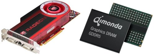
A Radeon HD 4870 graphics card and its Qimonda GDDR5 memory chip (circa 2008)
Video memory technologies will no doubt continue to evolve at a rapid pace, along with display adapter technology generally. Whilst the capacity of the video memory is important for storing both the image data and the intermediate results of the calculations required to populate the frame buffer, bandwidth (the total amount of memory that can be accessed in a given time frame) is also a crucial factor in determining performance.
The bandwidth will be the factor that determines the maximum frame rate that can be achieved. Note that frame rate refers to the speed at which new images can be generated and sent to the frame buffer. It should not be confused with refresh rate, which is the speed at which each screen image is re-written (refreshed) by the monitor.
RAMDAC stands for Random Access Memory Digital to Analogue Converter. The majority of monitors used with personal computers, from the introduction of VGA display adapters in 1987 until the end of the 1990s, were cathode ray tube (CRT) devices that required analogue signals to drive the display. Computers are purely digital devices, so naturally the image data generated by the display adapter and stored in the frame buffer is digital. Before it can be interpreted by the analogue monitor hardware, the digital data must be converted into an analogue format.
The RAMDAC reads the digital image data stored in the display adapter's frame buffer, and converts it into analogue RGB signals. These signals determine the intensity of the red, green and blue (RGB) components of each pixel. There is a separate digital-to-analogue converter (DAC) in the RAMDAC for each of the RGB components. Each DAC produces a different signal voltage, which is sent along the cable that connects the display adapter to the monitor.
The CRT monitor uses the RGB signals to control the operation of three electron guns (one for each colour). The electron guns traverse the screen horizontally and vertically in order to fire a stream of electrons at phosphor dots on the inner surface of the CRT screen, creating the colour for each pixel. The guns traverse one row of pixels at a time, and the signals from the RAMDAC control the intensity of the beam fired by each electron gun at each pixel. The entire operation occurs at a frequency of up to one hundred cycles per second.
Over the last decade or so, CRT monitors have largely been replaced by flat screen LCD monitors that are less bulky and more power efficient. The change was gradual at first because the first flat screen products on the market were expensive, and in many cases the early offerings did not produce particularly good quality screen displays by comparison with CRT monitors. For this reason, most display adapter manufacturers continued for some time to produce graphics cards that only had the standard 9-pin VGA analogue output port, despite the fact that the new LCD displays were digital devices. The LCD displays had to convert the incoming analogue signal back into a digital format in order to display the images correctly.
The speed at which the RAMDAC can read the contents of the frame buffer and carry out the necessary digital-to-analogue conversion is a limiting factor in terms of the refresh rates supported by the display adapter. Many display adapters now offer both analogue and digital outputs, and some only provide a digital output. Likewise, most LCD monitors have both analogue and digital ports, with some only providing a digital interface (the subject of display adapter ports is dealt with in more detail later on this page).
Once a separate component on the graphics card, the functionality of the RAMDAC is now usually integrated into the display adapter's GPU. Eventually, there will be no requirement for any digital-to-analogue conversion and the RAMDAC will probably disappear.
Like the system motherboard, the modern graphics card comes with its own basic input-output system (BIOS) chip that performs much the same function for the display adapter hardware that the main system BIOS performs for the system as a whole. It performs power-on self-test (POST) diagnostic functions such as testing the video memory.
Most modern graphics cards support the VESA BIOS Extensions (VBE) which provide a standard interface to the display adapter hardware for application software. VBE allows an application to detect the display modes supported by the graphics card, and to set the mode required by the application. It also allows the display adapter to communicate with monitors that support display power management signalling (DPMS), enabling the monitor to be put into the appropriate power saving mode when not in use.
A display adapter vendor or chipset manufacturer will often provide updates for video BIOS firmware that can be downloaded from their website. As with all forms of firmware upgrade, it is important to make sure that the upgrade software (usually called a flash utility) exactly matches the video BIOS present on the display card. The vendor's upgrade instructions should be followed precisely, as failure to carry out a firmware upgrade correctly can render the card inoperable. On some of the more recent graphics cards, the video BIOS has user-configurable settings that can be accessed through a special setup program.
The video system interface defines how the display adapter is connected to other internal system components such as the CPU and main system memory. The amount of data being transferred over this interface has grown rapidly, and has driven the development of new and faster internal buses more than any other single factor.
Many of the earliest video cards were connected to the computer's motherboard via an ISA expansion slot. The first ISA bus was featured on IBM's XT personal computer and had a bus width of 8 bits (i.e. it could transfer 8 bits of data in parallel) and a clock frequency of 4.77 MHz. The IBM AT personal computer introduced an ISA bus with a width of 16 bits and a clock speed of 8.33 MHz.
IBM doubled the bus width again to 32 bits in 1987 with its proprietary micro-channel architecture (MCA), which was a feature of the new PS/2 personal computer. Despite the fact that the MCA bus ran at a frequency of 10 MHz, it proved less popular than either ISA or the 32-bit 8.33 MHz extended ISA (EISA) interface that succeeded it in 1988 due to its proprietary nature and cost. Unlike MCA, the new EISA interface was compatible with many of the older ISA cards. Despite some success in the server market for EISA-based disk controller and network cards however, EISA was not widely adopted for use in desktop personal computers. Both EISA and MCA soon passed into obscurity.
The early bus standards mentioned above provided relatively low bandwidth that was usually shared between two or more attached devices. The concept of bus mastering was developed to allow a specific device to take control of the bus for its own purposes, and to access the system memory directly. As the data transfer rates required by display hardware increased, the bandwidth available on the ISA bus proved increasingly unable to meet the demand. Consequently, the idea of a local bus connecting one or more expansion slots directly to the CPU was born.
The first local bus to be developed was the 32-bit VESA local bus (VLB) introduced in 1992, and clocked at 33 MHz. Although providing far higher bandwidth than ISA the VLB was not without problems, and its popularity waned after a couple of years as the peripheral component interface (PCI) started to appear on Pentium-based IBM personal computers and their clones from 1993 onwards. PCI resurrected the concept of a shared bus that implemented bus mastering, and could compete with the VESA local bus in terms of performance.
PCI initially provided a bus width of 32 bits and a bus frequency of 33 MHz, although bus width was later increased to 64 bits with the PCI-Extended (PCI-X) interface, which supported bus speeds of up to 133 MHz. It solved many of the problems that dogged the VESA local bus, and was the first interface to feature a Plug and Play capability in which system resources could be allocated to peripheral devices through software rather than by using manual setup procedures that involved setting jumpers or switches.
The first bus interface specifically dedicated to graphics data was the Accelerated Graphics Port (AGP) interface that appeared in 1997 on computers featuring Intel Pentium 4 or AMD Athlon XP processors. AGP provides a dedicated bus between the display adapter hardware and the memory controller hub (or Northbridge) on the computer system's motherboard. Unlike PCI, the shared nature of which dictates that attached devices run at some predetermined fraction of the front side bus (the bus connecting the Northbridge to the CPU), the AGP interface can theoretically offer the same bandwidth as the front side bus.
AGP version 1.0 initially provided a 32-bit bus with a clock frequency of 66 MHz, and could transfer 32 bits of data per clock cycle. This mode was known as 1x because it provided the same maximum data transfer rate (267 megabytes per second) as a 64-bit, 33 MHz PCI-X bus. AGP version 1.0 also supported a 2x mode that doubled the throughput to 64 bits of data per clock cycle for a data throughput of 533 megabytes per second.
AGP version 2.0 display adapters used a lower voltage, required a longer slot on the system motherboard, and supported 1x, 2x and 4x (1,067 megabytes per second) modes. AGP 3.0 is the most recent and effectively the final version of AGP, and supports 4x and 8x (2,133 megabytes per second) modes. Motherboards supporting the AGP interface have gradually been phased out over the last few years in favour of the newer PCI Express interface.
An AGP 3.0 display adapter slot
PCI Express (PCI-E) first appeared in 2004 and is the most recent standard for display adapter cards at the time of writing. Many devices currently on the market support the version 2.x specifications (the specification for version 3.0 was published in November 2010). Newer versions of the standard are designed to be backwardly compatible with previous versions, and graphics cards designed for PCI-E 1.x should work on motherboards that provide PCI-E 2.x slots.
PCI-E differs fundamentally from the original PCI in that it provides dedicated point-to-point serial links between two devices, rather than sharing the bandwidth of a single parallel interface. A single PCI-E link is a full-duplex (two-way), four-wire channel known as a lane. Data is transmitted in packets, each of which includes the address of its destination node, over a packet switched network.
The network consists of a series of point-to-point connections linking devices to each other, the CPU and system RAM via a switch (called the root complex) built into the motherboard. The slowest kind of link on the network is a 1x link that consists of a single lane. Standard PCI-E link designations are 1x, 2x, 4x, 8x, 16x and 32x (the number in front of the x represents the number of lanes used).
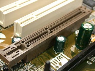
Motherboards currently on the market typically provide one PCI Express 16x slot and one PCI Express 1x slot, as well as a couple of standard PCI slots. Most graphics cards currently on the market require a PCI-E 16x slot. Note that the size of a PCI-E slot will depend on its designation (1x, 4x, 16x etc.), and whilst a PCI-E device designed for a 1x slot will usually fit into and work in a larger slot, the reverse is not generally true. Note also that because the PCI-E root complex is bridged to the PCI bus, you should also (in theory) be able to plug older PCI devices into a PCI Express slot, if it is long enough.
Some high-end motherboards offer two or more PCI-E 16x slots, allowing multiple display adapters to be installed. Some high-end graphics cards can support up to three monitors each, so in theory two high-end graphics cards installed on the same motherboard would enable a computer to output different displays to six monitors simultaneously!
The data rates supported by PCI-E were from the beginning much faster than those previously achieved. PCI-E version 1.x operates at a bus frequency of 2.5 GHz and provides a data rate of 250 megabytes per second per lane. PCI-E version 2.x doubles the bus frequency to 5 GHz and the data rate per lane to 500 megabytes per second, giving an aggregate data rate for a 16x link of 8 gigabytes per second.
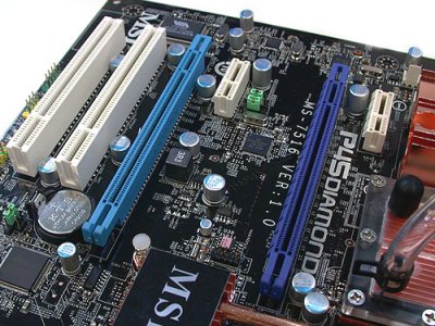
This motherboard features two 16x and two 1x PCI-E slots, and two PCI slots (far left)
Driver software provided by the display adapter vendor or chipset manufacturer provides the interface between the display adapter and the computer's operating system. A new graphics card purchased for a system upgrade will invariably be accompanied by a CD-ROM containing driver software, utilities and tools. The bundled software may well include image manipulation software as a value-added feature.
Thanks to the rapid speed of developments in the world of graphics hardware and software, the driver provided is often out of date by the time the card is sold, so a visit to the chipset manufacturer or vendor's website may be required in order to retrieve the most up-to-date versions of drivers and utilities. Note that an operating system vendor will usually provide generic display adapter drivers for standard VGA display modes and may provide their own drivers for specific hardware products, but it is preferable to use the manufacturer's own driver software.
Some applications, particularly games, will only function correctly with the latest drivers. For laptop and netbook computers that tend to have a highly customised hardware configuration, it may be necessary to obtain drivers from the computer manufacturer.
While the driver software provides a basic interface between the operating system and the display adapter hardware, many applications including games require an additional programming interface in order to take advantage of the 3D capabilities of the graphics card. This application programming interface (API) is provided by a standard library of programming functions such as Microsoft's DirectX (currently in version 11), which is actually a collection of APIs that handle various aspects of graphics programming.
Many graphical applications written for the Windows operating system, including games, come with the required version of DirectX. One of the features of DirectX is its ability, in some cases, to emulate missing hardware functionality in order to enable application software to run even if the hardware itself lacks certain required features. Software that achieves this is said to have a hardware abstraction layer (HAL). Clearly however, performance in such cases is not going to be as good as it would be if the functionality were fully implemented in hardware.
Silicon Graphics have developed their own cross-platform standard API, called the Open Graphics Library (or OpenGL) that provides much the same kind of functionality for application programmers as DirectX. Many current display adapters feature GPUs that support both standards.
For reasons already mentioned, producers of display adapters and computer monitors have continued to support the 9-pin D-sub (DE-9) connectors that first appeared with IBM's PS/2 personal computer, which required an analogue display unit. Nearly all display adapters and computer monitors currently on the market now provide digital ports, with many continuing to support VGA connections and some offering a range of connection types.
The most common type of digital interface currently provided is the digital visual interface (DVI). DVI ports come in four main flavours, as shown in the diagram below. The first distinction to be drawn is between single link and dual link configurations. Single link DVI connections have eighteen digital pin connections and can handle screen resolutions of up to 1,920 x 1,200 pixels, but many graphics cards can now output images at the much higher resolutions that can be displayed on (typically) 30 inch monitors. More signal lines are needed for these higher resolutions, and these can be provided via DVI dual link connectors that have an additional six digital pin connections.
DVI port configurations
A second distinction is between DVI-I connectors that provide both digital and analogue output signals and DVI-D connectors that provide only digital output. DVI-I connectors are characterised by an additional four pin connections to the left of the main body of the connector as illustrated above. These pins carry analogue signals, allowing a DVI-I port to be connected to an analogue display unit.
If a CRT or LCD monitor only has a VGA D-sub 9-pin connector, the connection can be made using a suitable adapter cable. Many graphics cards currently on the market have either one or two DVI ports, as well as a VGA D-sub port. It is often possible to connect two display units to a single display adapter in order to split the display output across the two screens.
A new digital interface called DisplayPort was introduced in 2006 that is intended to eventually replace both VGA and DVI connections between computers and their display units. DisplayPort has started to appear on a small number of graphics cards, monitors, and laptop computers, and is forecast to increase its market share steadily over the next three to four years as support for VGA is phased out.
Many high-end graphics cards provide ports to enable a computer to be connected to video recording and television equipment, as well as DVD players and game consoles. A 9-pin mini-DIN port can be used to allow analogue video input and output between the display adapter and an attached device via an appropriate cable. This video in video out capability is often referred to using the acronym VIVO, and typical uses include being able to display computer-based media on a TV screen, or record television programmes on a computer (note however that some graphics cards that provide a 9-pin mini-DIN port only support video output).
A number of graphics cards are now also providing a high definition media interface (HDMI) port to enable the computer to be linked to HD ready LCD television sets.
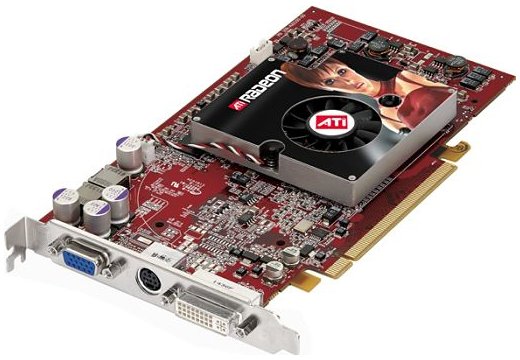
A Radeon X850 XT graphics card with VGA, VIVO and DVI-I ports
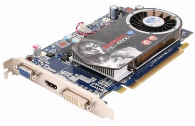
A Radeon HD4650 graphics card with VGA, HDMI and DVI-I ports
ATI (now AMD) and NVIDIA have developed competing technologies to allow two or more graphics cards to be installed on a single motherboard to create a single output with improved graphics performance. The motherboard must of course support these technologies (many motherboards now provide support for both), and must provide the required number and type of PCI Express slots.
The ATI technology is called CrossFire and first appeared in 2005. It initially required two Radeon x800, x850, x1800 or x1900 graphics cards, one of which had to be a CrossFire Edition version (the other had to be a standard version). The CrossFire Edition card acts as a master card, combining the outputs of the two cards together. The cards themselves had to be from the same product family, and were linked using a proprietary dongle that plugged into the primary DVI output port on each card. The dongle provided a separate connection for the monitor cable.
Later versions of the technology removed the need for a dongle, and for the presence of a CrossFire Edition master card. The two CrossFire enabled cards are still linked together via a ribbon cable attached to connectors located at the top of each card. In some configurations, communication between the cards may take place instead via the PCI Express bus provided appropriate driver software is available, although this has an impact on performance.
Recent developments include enhancements to the CrossFire technology that allows it to support for up to four graphics cards mounted on the same motherboard. Since 2008, some dual-GPU cards can operate in CrossFire mode utilising an on-board PCI Express bridge, and two such cards can be linked together to provide a four-GPU CrossFire capability.
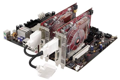
Two ATI Radeon graphics cards connected by a CrossFire dongle
The NVIDIA technology is called Scalable Link Interface (SLI), and first appeared under that name in 2004. Like ATI's CrossFire technology, SLI initially required two (preferably identical) graphics cards to be installed in PCI Express 16x slots in a master-slave configuration. Motherboards that supported SLI provided a customised slot between the two PCI-E 16x slots into which a special paddle card was inserted.
The purpose of the paddle was to channel either 16 PCI-E lanes to the PCI-E slot holding the master SLI card, or 8 lanes to each card's slot, depending on which way round it was inserted. This was necessary because motherboards of the time simply did not have enough PCI-E lanes to provide 16 lanes to each slot (this is not a problem on current motherboards).
The cards are interconnected by a short printed circuit board called the SLI bridge that plugs into both SLI cards and allows data to be transferred directly between the cards. The combined output is sent to the monitor via the master SLI card. Two low-end NVIDIA cards can also run in SLI mode without an SLI bridge by communicating via the PCI-E bus, since the bandwidth required is far less than that needed by high-end cards.
Various configurations have emerged for graphics cards with dual GPUs. Most of these configurations involve GPUs mounted on two separate printed circuit boards (PCBs) that either have their own cooling units or a shared cooling unit. The PCBs are connected by an SLI and a separate dedicated PCI-E 16x link. The PCB holding the GPU that is designated as the master GPU is connected to a PCI-E 16x slot on the motherboard.
These dual-GPU cards have an on-board PCI-E bridge chip with 48 lanes that provide the same functionality as the media communications processor (MCP) that must normally be present on the motherboard in order for two graphics cards to be able to operate in SLI mode. This essentially means that the cards can run in SLI mode on a motherboard that does not specifically support SLI. As with CrossFire, two dual-GPU SLI graphics cards can be paired on an SLI motherboard and bridged to provide a four-GPU capability.
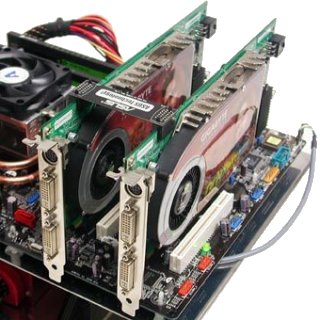
Two NVIDIA graphics cards connected by an SLI bridge