| Author: | |
| Website: | |
| Page title: | |
| URL: | |
| Published: | |
| Last revised: | |
| Accessed: |
The computer's power supply unit (PSU) converts the domestic alternating current (ac) mains supply voltage (220-240 volts in Europe) into various regulated, low voltage direct current (dc) outputs required by the components that make up the computer system.
The PSU usually takes the form of a metal box 150mm wide x 86mm high x (typically) 140mm deep. It is mounted inside the system case using four screws in a standard location such that the on/off switch and power cord socket mounted on the back of the PSU are accessible via an aperture in the rear of the case. The same aperture also allows air to flow into the PSU's cooling fan.
In some cases, there may be a voltage selector switch to allow the user to select a voltage according to their geographical location (the United States, for example, has a domestic power supply operating at a nominal 120 volts). Inside the case, a bundle of cables emerges from the front of the PSU. The cables are often grouped and colour-coded according to the type of device they will be connected to.
Although in the past several form factors have been used for the power supply unit, some of them quite heavy and bulky, most desktop personal computers now use power supplies that conform to the standard ATX format, the most recent version of which is 2.3.1 released in 2008. The illustration below shows a typical ATX PSU.
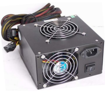
A typical ATX power supply unit
ATX PSUs are designed to work specifically with the ATX family of motherboards and fit into an ATX system case, and can be turned on or off (or placed into standby mode) using signals generated by the motherboard. The maximum rated power output of a PSU can range from around 250 watts up to as high as 2 kilowatts, depending on the type of system they are intended for.
Small form factor computer systems tend to have low power supply requirements in the order of 300 watts or less. Systems used for gaming have much higher power requirements (typically 450 to 800 watts), mainly because they employ high-end graphics adapters which consume large amounts of power. The highest power consumption is found in commercial network servers or high-performance personal computers featuring multiple processors, a number of disk drives, and multiple graphics cards.
The amount of power required by a particular computer system will depend on the power requirements of the motherboard, processor and RAM, and on the number of add-on cards and peripheral devices drawing power from the PSU. In reality, few personal computers currently need more than about 350 watts.
Even so, care should be taken when selecting a power supply unit, since the rated maximum power output claimed by some manufacturers does not always reflect the actual power output that can be achieved under various load conditions. As a result, manufacturers and vendors of PC systems and system components (especially high-end graphics cards) have a tendency to over-specify the minimum power requirements when it comes to recommending a power supply rating for PSUs to be used with their products.
Whilst it is true that an inadequate power supply can fail if it becomes overloaded, it is not a good idea to use a high-output power supply regardless of the actual power requirements. On the contrary, you should select a PSU with a power output that reflects the power requirements of the system. Energy efficiency is at its highest when the load on the power supply is between 50% and 75% of the maximum output. This means that the PSU dissipates less power as heat.
If the PSU fan speed is being regulated by the motherboard, as is often the case, the system will run more quietly because less airflow is required to cool the PSU. At low loads (less than 20% of capacity), energy efficiency drops significantly and more power will be dissipated as heat than would be the case in a more appropriately rated PSU. Even worse, if the load drops below 15% of capacity the PSU may not function properly, and there is a good chance that it will shut down altogether.
The information supplied on the label or plate attached to the power supply provides technical information about the power supply which will include the ac mains supply voltages, currents and frequencies that the unit can be used with, the maximum total power output in watts, and the various dc voltage and current outputs available. It will also display hazard warnings and the required safety certification information (in Europe, this is the CE mark). A typical PSU label is shown below.
An example of the information provided on a PSU
The connectors provided can vary from one model to another, but those typically included are summarised in the table below.
| Type | Description | Illustration |
|---|---|---|
| P1 | A 20-pin or 24-pin connector that provides power to the motherboard. On some PSUs, the P1 is split into one 20-pin connector and one 4- pin connector which can be combined if required (see illustration) to form a 24-pin connector. | 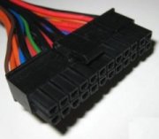 |
| ATX12V (or P4) | A 4-pin power connector that goes to the motherboard in addition to a 20-pin P1 to supply power to the processor. | 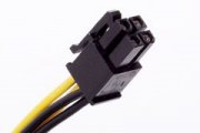 |
| Molex | A 4-pin peripheral power connector that supplies power to IDE disk drives and CD- ROM/DVD drives. | 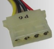 |
| Berg (or Mini- Molex) | A 4-pin power connector that supplies power to the floppy disk drive (it can also be used as an auxiliary connector for AGP video cards). | 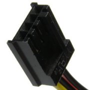 |
| Serial ATA | This is a 15-pin power connector mainly used for SATA hard drives. | 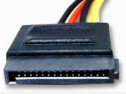 |
| PCI Express | A 6-pin or (more recently) 8-pin power connector used for PCI Express graphics cards. Some 8-pin connections allow for either a 6-pin or an 8-pin card to be connected by using two separate connectors on the same cable (one with 6 pins and another with 2 pins). | 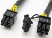 |
The positive output voltages produced by a power supply unit are +3.3V, +5V and +12V. Negative voltages of -5V and -12V are also provided, together with a +5V standby voltage. Different voltages (sometimes referred to as rails) are used to power different components, and a summary of which voltages and (and currents) are used for what purpose is given below.
For those unfamiliar with the concept of negative voltages in dc circuits, this simply means that the potential difference is measured from ground to the signal rather than the other way round (ground is commonly used as a reference point for measuring voltage). The current requirements of the various system components are significant, because power is the product of voltage and current. The total power requirements of the system thus depend on the voltage and current requirements of its individual components.
| Voltage | Purpose |
|---|---|
| -12V | Used on some older types of serial port amplifier circuits. Generally unused on newer systems. Current is usually limited to 1A. |
| -5V | Used on some early personal computers for floppy disk controllers and some ISA add-on cards. Generally unused on newer systems. Current is usually limited to 1A. |
| 0V | The zero volt ground (also called common or earth) and reference point for other system voltages. |
| +3.3V | Used to supply power for the processor, some types of memory, some AGP video cards, and other digital circuits (most of these components required a +5V supply in older systems). |
| +5V | Still used to supply the motherboard and some of the components on the motherboard. Note that there is also a 5V standby voltage present when the system is powered down which can be grounded (e.g. by the user pressing the power switch on the front of the case) to restore power to the system. |
| +12V | Primarily used for devices such as disk drives and cooling fans which have motors of one sort or another. These devices have their own power connectors that come directly from the power supply unit. |
The type of power supply unit found in a modern PC is referred to as a switched mode power supply unit (SMPSU). What this means in essence us that the ac mains voltage coming into the PSU is rectified to produce a dc voltage without using a mains transformer (these are usually rather heavy due to the need for a coil with a ferrite core). The voltage thus obtained is then switched on and off at very high speeds using electronic switching circuitry, effectively producing a high-frequency square wave voltage (effectively, a series of dc pulses). A light and relatively inexpensive high-frequency transformer can then be used to produce the required dc output.
The dc output voltage and current are regulated (kept constant) using a feedback controller that increases or decreases power output in accordance with variations in load current. It does this by increasing or decreasing the duty cycle (essentially, this means increasing or decreasing the number of voltage pulses produced by the switching circuitry in a given time frame).
Note that most PSUs can shut themselves down if load current exceeds a certain threshold, reducing the possibility of damage to the computer system (or its user) in the event of an electrical fault such as a short circuit. The same principle applies to the absence of a load current (or a very low load current), since the PSU cannot operate correctly below a certain power output level and will shut down if insufficient load current is detected.
When first turned on, it can take half a second or so for the power supply to stabilise and start generating the correct dc voltages required by the computer. The power supply therefore sends a signal to the motherboard called the Power Good signal, once it has carried out its internal tests and is satisfied that the power outputs are all as they should be. The motherboard must wait for this signal before powering up the system.
A power surge or momentary power failure will sometimes cause a short interruption in the Power Good signal, which will cause the system to reboot when it is resumed. Note also that for practical reasons the different voltages produced by a power supply unit are actually produced by several different switched-mode supplies that are linked together within the PSU, each of which varies its output according to component power requirements.
One recent trend in PSU design has been the concept of a modular power supply, in which cables can be attached to the PSU via connectors at the power supply end, allowing the user to install only the cables they actually need. The idea is that the omission of cables that are not required will reduce clutter inside the case and improve airflow. It also provides more choice in the type of power cable the user can install (e.g. Serial ATA or Molex for hard drives).
Critics of this development have pointed out that electrical resistance will be increased due to the greater number of electrical connections. Proponents point out that the increase in resistance is very small. In practical terms however, problems are only likely to occur if the connectors are old and worn (in which case the connection may be a loose one) or the connection has not been made correctly during installation. The obvious answer is to replace old cables and check all connections prior to first use. The main PSU connectors and their pin outputs are illustrated in the diagram below.
Common PSU connectors and their pin outputs
Power supply failure will invariably require the replacement of the PSU, since the computer will obviously not function without it. Such failures often result from overheating due to the breakdown of the cooling fan. The system subsequently powers itself off and cannot be rebooted or, as sometimes happens, repeatedly reboots itself at apparently random intervals.
In critical computer systems such as network servers, it is not uncommon to find redundant power supplies acting as a backup for the main power supply. The backup unit takes over in the event of a failure in the primary power supply, which can then be replaced during a scheduled maintenance period.
At the other end of the scale, portable computers such as laptops and netbooks require far less power (200 watts or less) enabling them to be powered by a removable rechargeable battery which can easily be replaced if necessary. An external power supply is used to charge the battery, and can supply power to the system while it is connected. This external power supply unit typically supplies 19.5V direct current.
The facility to power the computer's power supply on or off by grounding the +5V standby voltage means that the system can be powered on or off by a signal generated by the motherboard in response to a software interrupt (or system call - a signal generated by the operating system) or a hardware interrupt (a signal generated by a hardware component on the system).
The ability to control power using a system call means that the user can power down the system by clicking on an icon or menu item rather than having to physically switch off the system using the power switch. It also means that power management software can be configured to power down the computer in the absence of user input for a given period of time. The system can be set to power on again in the event of some predetermined occurrence, such as the user pressing a key on the keyboard or the activation of a network connection.