| Author: | |
| Website: | |
| Page title: | |
| URL: | |
| Published: | |
| Last revised: | |
| Accessed: |
Modulation is the process of varying the properties of a periodic waveform in order to represent analogue or digital information. The periodic waveform used is called a carrier wave, and usually has a sinusoidal waveform. The property that is varied by the modulation process depends on the kind of modulation scheme being used. It could be the amplitude, frequency, or phase of the carrier wave, or even some combination thereof. The underlying reason for wanting to modulate an information-carrying signal onto a carrier wave in the first place is that the information signal itself is unsuitable for the transmission medium (typically a high-frequency radio channel or a microwave satellite link) over which we want to send it.
In part one of this article, we will talk in general about digital modulation - the transmission of a digital baseband signal using a high frequency carrier - and about two common forms of digital modulation, namely amplitude shift keying (ASK) and frequency-shift keying (FSK) . In part two, we will be looking at phase shift keying (PSK), and some of the more complex types of modulation scheme based on it.
Digital signals can be used to represent either digital or analogue information. The most basic form of digital modulation is on-off keying - a simple form of amplitude shift keying in which a high-frequency signal is turned on and off repeatedly in order to create a pattern of pulses representing the binary information we want to send. For example, the presence of a signal for a specific amount of time could represent binary one, while the absence of the signal for the same amount of time could represent binary zero.
On off keying is also used to send messages in Morse code, where groups of short and long pulses (usually referred to as dots and dashes) are used to represent alphanumeric characters. Named after its inventor, the American inventor and painter Samuel Finley Breese Morse (1791 - 1872), Morse code was first used in the 1830s to send messages via telegraph. It is still used today in the fields of aviation and maritime communication, as well as being popular with amateur radio enthusiasts, although its use is steadily declining. Morse code messages can be sent as pulses of light or as audible clicks, but they are most commonly transmitted via radio. The illustration below shows the 26 letters and 10 and numerals of the International Morse Code.
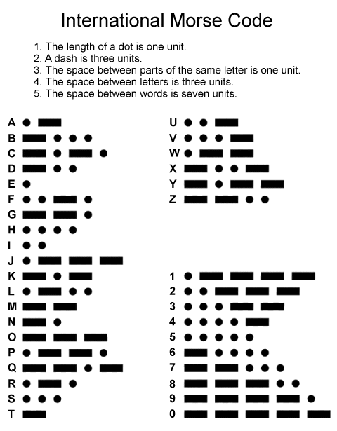
Chart showing the symbols used by the International Morse Code
Morse code can be considered to be a form of digital modulation, because the information used to modulate the carrier takes the form of a small number of discrete symbols - just two in fact (a dot and a dash) as you can see from the illustration above, although the spaces between the symbols can also have meaning in terms of separating words or characters.
The kind of modulation we want to investigate invariably involves the use of a relatively low frequency digital baseband signal - one that directly represents the information we want to transmit. This signal consists of a series of discrete pulses, and can be sent over fixed links consisting of twisted pair, coaxial, or fibre optic cables without the need for modulation (for a detailed discussion of the signalling schemes used for this purpose, see the article "Line Coding Techniques" in this section). For wireless transmission, however, the digital baseband signal is used to modify a high frequency carrier wave.
The different kinds of digital modulation we will be looking at in parts one and two of this article are briefly summarised in the following list:
As previously mentioned, the carrier used to transmit the digital information usually has a sinusoidal waveform, which means its amplitude varies continuously. For this reason, some sources consider digital modulation techniques to be a form of digital-to-analogue conversion (DAC). However, we should bear in mind that each digital modulation scheme assigns discrete values to some property of the sinusoidal wave (amplitude, frequency or phase) in order to represent the digital data being transmitted. Most texts therefore regard the signals produced by digital modulation schemes to be fundamentally digital in nature. The most basic forms of digital modulation (ASK, FSK and PSK) are represented below.
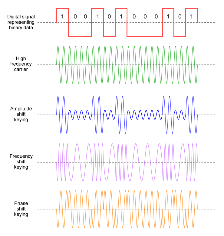
A time domain representation of ASK, FSK, and PSK
It is fairly obvious why we need to use digital modulation techniques to transmit digital data over a high frequency carrier. The reason we now use those same techniques to transmit analogue data (e.g. voice data or live television broadcasts) may not be quite so obvious. After all, it may require the analogue data to undergo analogue-to-digital conversion (ADC) at the transmitter before any digital modulation takes place, and at the receiver the demodulated signal must be converted back to its original analogue format in order to be intelligible to an end user. Nevertheless, digital techniques have replaced traditional analogue techniques for radio and television broadcasting, and even for most voice communication.
There are in fact a number of reasons why digital transmission is (usually) preferable to analogue transmission. One reason, of course, is that much of today's audio-visual content is already in digital format. More importantly, the use of discrete digital signalling - as opposed to a constantly varying analogue signal - makes it far easier to detect and correct transmission errors - something that is very difficult to do, and in many cases not even possible, with an analogue signal. Digital signalling also makes it possible to implement end-to-end data encryption, which has significant implications from the point of view of both data security and digital subscription services.
The spectral efficiency of a modulation scheme is a measure of how efficiently it makes use of the bandwidth available to it. Efficiency in this case equates to how many bits per second we can transmit for a given bandwidth. Spectral efficiency is of particular importance in radio frequency and microwave applications because of the huge and constantly growing demand for bandwidth in these areas. The spectral efficiency ηc of a given channel (also known as modulation efficiency or channel spectral efficiency), is defined as:
ηc = Rc /Bc
where Rc is the bit rate (or data signalling rate) of the channel in bits per second, and Bc is the channel bandwidth. For any given channel, these values are determined by the physical medium over which the data is transmitted and modulation scheme used. In order to calculate the bit rate, we need to multiply together the symbol rate (or baud rate), i.e. the number of signalling symbols that can be transmitted per second, and the number of bits represented by each signalling symbol. Note that the spectral efficiency of a channel is measured in bits per second per hertz (b/s/Hz).
Obviously, if we can increase the number of bits transmitted per baud without increasing the overall bandwidth requirement (and assuming that the baud rate itself is a constant), we can increase spectral efficiency significantly. For example, if we modulate a carrier using amplitude shift keying (ASK), we can use 16 different amplitude levels instead of 2 in order to send 4 bits per baud instead of just 1. It is easy enough to build a transmitter that can generate a 16-level digital signal.
We must remember, however, that all communication channels - especially wireless channels - are subject to noise. Much of this noise is thermal noise, which arises in electrical and electronic circuits due to the random movement of electrons, and cannot be eliminated. Noise causes transmission errors, and thus has a significant impact on the information rate, i.e. the number of useful bits of information transmitted per second as opposed to any signalling overhead and error correction codes used (see below).
In order to be able to correctly demodulate an incoming signal, the receiver must be able to distinguish between the transmitted signal and any background noise. The extent to which this can be achieved depends on the signal-to-noise ratio (SNR), i.e. the ratio of signal power to noise power. As this ratio becomes smaller, the receiver will find it increasingly difficult to detect changes in the amplitude, frequency or phase of the incoming signal.
The bit error rate (BER), i.e. how many bit errors occur per unit time, depends on the extent to which the receiver can correctly decode the incoming digital signal. A bit error occurs when a bit is altered during transmission due to noise, or some other kind of transmission impairment, causing it to be incorrectly interpreted by the receiver. If we divide the number of bit errors that occur during a given time interval by the total number of bits transmitted during that time interval, we get the bit error ratio (also BER), which is usually expressed as a percentage.
The impact of bit errors will depend on the type of information being transmitted. For voice transmissions, streaming media, and radio and television broadcasts, the occasional bit error will not cause a problem and will usually not even be noticed. For data transfers, on the other hand, a single bit error can render an entire data packet invalid, requiring it to be retransmitted. This problem can usually be avoided by including adequate forward error correction codes (FECs) to the transmitted data, enabling the receiver to detect and correct errors without having to request a retransmission. Bear in mind, though, that this can add a significant amount of redundant data to each packet transmitted.
The theoretical maximum data rate of a channel in bits per second is known as the channel capacity C. It is determined by how noisy the channel is and the channel bandwidth, in accordance with the Shannon-Hartley law:
| C = B log(2) | ( | 1 + | S | ) |
| N |
Where B is the analogue bandwidth of the channel and S/N is the signal-to-noise ratio. The maximum bit rate achievable is thus directly proportional to bandwidth, and logarithmically proportional to the signal-to-noise ratio, i.e. directly proportional to the logarithm of the SNR.
Of the digital modulation schemes outlined above, amplitude shift keying (ASK) is perhaps the easiest and most cost effective to implement. However, because it represents data solely as variations in the amplitude of the carrier, it is also far more susceptible to noise than other forms of digital modulation; noise affects the amplitude of a signal far more than it affects frequency or phase. As a result, ASK performs poorly in noisy environments, and is rarely used on its own for high-speed RF applications. It does perform rather well, however, on short-haul copper and fibre links in Ethernet networks, where it tends to be known as pulse amplitude modulation (PAM).
The spectral efficiencies of the other types of digital modulation we shall be looking at are summarised in the table below.
| Type of modulation | Spectral efficiency (b/s/Hz) |
|---|---|
| FSK | < 1 (depending on modulation index) |
| BPSK | 1 |
| QPSK | 2 |
| 8-PSK | 3 |
| 16-PSK | 4 |
| 32-PSK | 5 |
| 4-QAM | 2 |
| 16-QAM | 4 |
| 64-QAM | 6 |
Note that we have not included values for M-ary FSK modulation schemes - i.e. FSK schemes that use multiple frequencies to represent different bit patterns. These schemes have been used in the past for reliable and power-efficient communications, and are still used for some low-speed applications. They are however unsuitable for high-speed RF data communications because the spectral efficiency η of M-ary FSK modulation schemes actually decreases as the required number of signal symbols (known as the modulation order, M) increases. This is expressed by the following formula:
| η = | 2 log(2) M |
| M |
We have already mentioned the most basic forms of digital modulation, i.e. ASK, FSK and PSK. We should point out, however, that there are numerous variants of these basic modulation schemes. In the simplest version of each, the relevant signal characteristic, i.e. the amplitude, frequency or phase of the carrier, is switched between two possible values, one of which represents binary zero, while the other represents binary one. These simple versions are sometimes known as binary methods, and are denoted by placing the word binary in front of the scheme name. Thus ASK becomes BASK (binary amplitude shift keying), FSK becomes BFSK (binary frequency shift keying), and PSK becomes BPSK (binary phase shift keying).
If we are able to use more than two discrete values for a given signal characteristic, however, we can represent more than one bit per signal symbol, increasing the spectral efficiency of our modulation scheme. Let's suppose we want to represent two bits per signal symbol. For a 2-bit number, there are four possible bit patterns (00, 01, 10, and 11) so we need four different signal symbols to represent the four possible bit patterns. In other words, we need four values for amplitude, frequency or phase. That's twice as many different values as for a simple binary scheme. It turns out that, for each additional bit we want to represent per signal symbol, we need to double the number of unique signal symbols. If we let the number of symbols required be M, we can calculate M as follows:
M = 2 n
where n is the required number of bits per symbol. Thus, in order to represent four bits per symbol, we would require sixteen unique signal symbols (M = 2 4 = 16). We would thus need to generate 16 different signal amplitudes, frequencies, or phase angles in order to represent 4 bits per symbol (note that, usually, each amplitude, frequency or phase angle represents the same number of bits). The range of symbols used for a given digital modulation scheme is sometimes known as its alphabet, and each symbol represents a unique bit pattern (sometimes referred to as a message) consisting of n bits. We can rewrite the above formula to get the number of bits per symbol:
n = log2 M
Increasing the number of bits per symbol can reduce the bandwidth needed in order to achieve given bit rate. Conversely, it can enable us to increase the bit rate achievable over a channel that has a fixed bandwidth. This increase in bandwidth efficiency cannot be considered in isolation, however. We also need to take into account the effects of noise, and the susceptibility of a particular modulation scheme to said noise, since this will determine how much redundant data we need to transmit in the form of forward error correction codes in order to maintain the bit error rate at an acceptable level.
We have already briefly talked about the susceptibility of amplitude shift keying to noise, which tends to rule out multi-level ASK schemes for high-speed RF applications, despite the ease with which they can be implemented. In similar vein, multi-level FSK schemes are also not suitable for high-speed RF applications thanks to the fact that they are simply not bandwidth efficient (see above). As we shall see in part two of this article, most of the M-ary digital modulation schemes in widespread use today are based on phase shift keying (PSK), often in conjunction with binary ASK, or using two carriers in quadrature (we'll be looking at what that means next), or with some combination thereof.
There are a number of digital modulation schemes whose name starts with, or includes, the word quadrature - for example, quadrature amplitude modulation (QAM). This indicates that the information signal is used to modulate not just one but two separate carrier waves, out of phase with each other by exactly 90 degrees. When two signals are out of phase like this, they are said to be in quadrature, or orthogonal, because the phase difference between them is one quarter of a cycle.
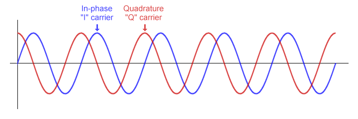
Two carrier waves 90 degrees out of phase are said to be in quadrature
The information to be transmitted is effectively split into two data streams at the transmitter, each of which is used to modulate one of the carriers. The two modulated carrier signals are then added them together, and the combined signal is transmitted. The receiver separates the incoming signal into its constituent parts and demodulates each in order to recover the two data streams, which it then recombines in order to re-create the original information signal.
The generally accepted convention is to consider one of the carriers to be the in-phase or I-carrier. The other carrier, which is 90 degrees out of phase with the I-carrier, is called the quadrature or Q-carrier. Each carrier can be modulated using single-level or multi-level shift keying. The type of modulation used can be amplitude, frequency, or phase shift keying, or some combination thereof. Quadrature amplitude modulation (QAM) is an example of this type of modulation. Each of the two carriers is modulated using amplitude shift keying (ASK). The transmitted signal consists of the modulated I and Q carriers, added together.
The basic quadrature modulator circuit consists of a local oscillator, a frequency-shifting network, two mixers, and an adder circuit. It takes as its input two data streams (the I-input and the Q-input) which are used to modulate the I-carrier and the Q-carrier respectively. The local oscillator generates the high-frequency carrier signal. Each mixer has two inputs and one output. The first mixer receives the in-phase carrier signal on one of its input and the I-input data stream on the other, and outputs the modulated I-carrier signal.
The second mixer also receives the carrier signal generated by the local oscillator, via the phase-shifting network. The phase-shifting network shifts the carrier's phase by 90 degrees to produce the Q-carrier signal. The resulting output from the second mixer is thus the modulated Q-carrier. The modulated I-carrier and Q-carrier signals form the two inputs to the adder circuit, which sums them and outputs the resulting signal to the transmitter. The illustration below is a block diagram of a generic quadrature modulator.
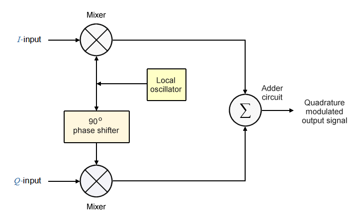
Block diagram of a generic quadrature modulator
Note that, despite implying that each carrier is modulated using ASK, the term quadrature amplitude modulation is also used somewhat more broadly to refer to a whole family of modulation schemes, most of which do not rely solely on amplitude shift keying, but rather use a combination of (usually) amplitude shift keying and phase shift keying (it can also refer to a number of analogue quadrature modulation schemes).
Amplitude shift keying (ASK) is the digital form of amplitude modulation. ASK represents digital data by varying the amplitude of a carrier wave whilst keeping the frequency and phase of the carrier constant. In the simplest form of ASK, the presence of the carrier wave for a defined period of time (the bit time) represents a binary one, and the absence of the carrier for one bit time represents binary zero. This form of amplitude-shift keying is known as on-off keying (OOK), and can also be used to transmit Morse code (see above).
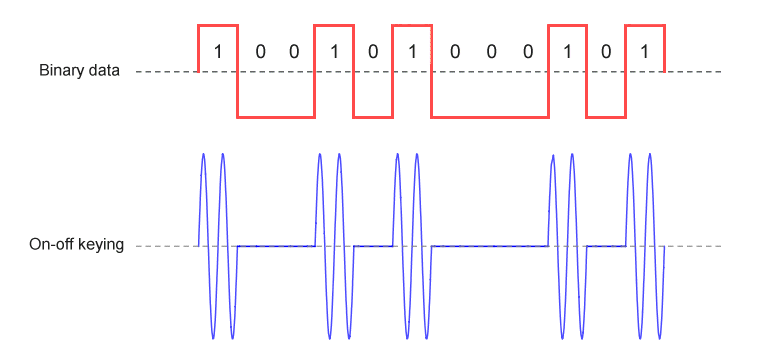
On-off keying is the most basic form of amplitude shift keying
An amplitude shift keying scheme in which the signal is varied between just two possible states is called binary amplitude shift keying (BASK). The on-off keying scheme shown above is one such scheme. In other BASK schemes, the signal amplitude is varied between a high amplitude and a much lower (but non-zero) amplitude, as shown below.
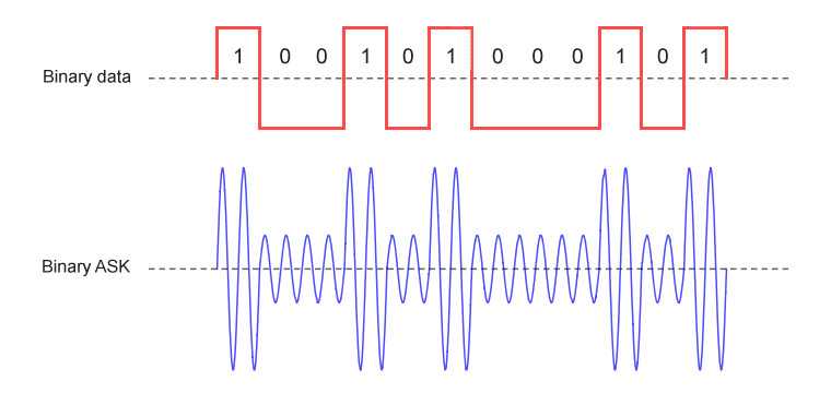
Some BASK schemes use a non-zero signal amplitude to represent binary zero
More elaborate forms of ASK use two or more signal levels in order to represent more than one bit per symbol. In order to represent two bits per symbol, for example, four different amplitudes are required, each of which represents a unique two-digit bit pattern (00, 01, 10, or 11). As previously mentioned, ASK is relatively simple and cost effective to implement but is more susceptible to noise than other forms of digital modulation. Increasing the transmitted power can mitigate the problem to an extent, but is not always desirable. The problem is compounded by the use of multi-level signalling, since the receiver must be sensitive enough to differentiate between several different signal levels.
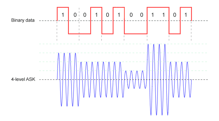
In 4-level ASK scheme, each signal level represents a unique 2-bit pattern
The block diagram below shows how a basic binary ASK modulator operates. The binary encoder takes a digital baseband information signal as its input and converts it to a unipolar NRZ binary signal, which forms one of two inputs to the product modulator. The other input to the product modulator is a high-frequency carrier signal generated by a local oscillator. The output of the product modulator is the instantaneous product of the binary input signal and the sign of the carrier signal. In the case of on-off keying, the modulator essentially acts as a switch, turning the carrier signal on or off to represent binary one or binary zero respectively. The bandpass filter limits the bandwidth of the transmitted signal to the band allocated for transmission.

Block diagram of a basic ASK modulator
There are two basic types of ASK demodulator - synchronous and asynchronous. We'll look first at how the asynchronous demodulator works. This kind of demodulation process is said to be asynchronous (or non-coherent) because it does not require the carrier signal to be replicated at the receiver. The illustration below shows a simplified block diagram of an asynchronous ASK demodulator.

Block diagram of an asynchronous ASK demodulator
The half-wave rectifier and the low pass filter act as an envelope detector in order to recover the unipolar NRZ binary signal generated at the transmitter. The incoming signal is rectified by the half-wave rectifier, generating a positive half-wave output. The low-pass filter then removes the high frequency components from the rectified signal.
The output from the envelope detector is a binary signal with two discrete voltage levels. This signal is passed to a voltage comparator whose reference voltage lies half way between the upper and lower binary signal voltages. The voltage comparator samples the binary signal in the middle of each bit time and compares the sample to the reference voltage in order to determine whether a one or a zero has been received.
Synchronous ASK demodulators are so called because they replicate the carrier frequency locally in order to demodulate the incoming ASK signal. The carrier signal can be generated by the receiver using various techniques, including the use of a phase-locked loop or narrow band filter to recover the carrier from the incoming signal. One fairly simple yet effective method is to apply some of the incoming signal to a high-gain circuit followed by a limiting amplifier that removes any variation in amplitude (i.e. the modulation), leaving just the carrier signal itself. A block diagram of a synchronous ASK demodulator is shown below.
The first element in the demodulator itself is a mixer, which takes as its inputs the incoming ASK modulated signal and the locally generated carrier signal. The output of the mixer is a signal consisting of the sum and difference of its inputs - a process known as heterodyning. The low-pass filter removes the high-frequency components, leaving just the low-frequency baseband modulating signal. A comparator is then used in the same way we saw with the asynchronous demodulator to determine whether a one or a zero has been received.
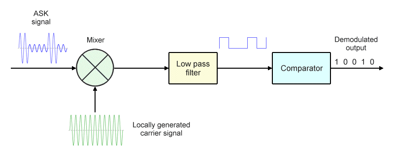
Block diagram of a synchronous ASK demodulator
Synchronous demodulators tend to provide better performance for signals that may be affected by fading, and also avoid some of the other problems that can arise with asynchronous demodulators such as the distortion that can occur within rectifier diodes. Synchronous demodulators require additional circuitry in order to replicate the carrier locally, which added cost and complexity to early ASK receivers built using discrete components. Today, however, the components needed for a synchronous demodulator can easily be incorporated in an integrated circuit at relatively little additional cost.
As previously mentioned, ASK is unsuitable for high-speed RF applications, and nearly all ASK applications use either BASK or OOK schemes that have just two signalling levels. ASK is typically used in low data rate, short-range applications such as near-field communication (communication between electronic devices four centimetres or less apart). Examples include electronic ID, key cards, and credit or debit cards that can be used for contactless payments. It is also widely used by many consumer electronics companies to implement remote control functionality in their products.
Frequency shift keying (FSK) is the digital form of frequency modulation. FSK represents digital data using discrete changes in the frequency of a carrier wave, whilst keeping the amplitude of the carrier constant. The simplest form of frequency shift keying, in which the binary logic values one and zero are represented by the frequency being shifted above or below the carrier centre frequency, is called binary frequency shift keying (BFSK). In conventional BFSK systems, the higher frequency represents a logic high (binary one) and is referred to as the mark frequency. The lower frequency represents a logic low (binary zero) and is called the space frequency. These two frequencies are equidistant from the centre frequency. A typical BFSK output waveform is shown below.
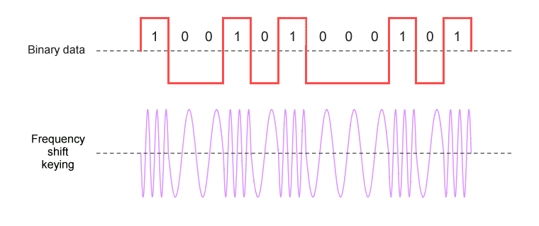
Binary frequency shift keying uses two discrete frequencies to represent binary data
FSK was used in modems and fax machines for data rates of up to 1200 bps, and is still used in a number of low data rate applications because it is both simple and reliable. Typical applications include paging systems, data collection (for example remote telemetry and metering), and remote control devices. Multilevel forms of FSK are used in 2-way digital radio, and are still used for Automatic Link Establishment (ALE) - the de facto standard for digitally initiating and maintaining HF radio communication. Coherent forms of FSK are also still used in Bluetooth and DECT.
The modulation technique used in most early modems and fax machines was known as audio frequency shift keying (AFSK) because the digital data was represented by changes in the frequency of an audio tone, which made it suitable for transmission on analogue telephone lines. Two tones were normally used to represent the mark and space values. Some early microcomputers used a modified form of AFSK to store data on audio cassettes.
A number of M-ary FSK schemes have been developed, although apart from the application areas mentioned above, most of these have been for military or amateur radio use. The spectral efficiency of M-ary FSK decreases with each increase in the value of M (the number of symbols in the modulation scheme's alphabet, usually a power of two) because the bandwidth requirement increases exponentially as M increases. Increasing the value of M also requires greater complexity in both the transmitter and the receiver, and increases the probability of transmission errors.
FSK requires more bandwidth than ASK for a given bit rate, and is thus less bandwidth efficient. However, an FSK signal varies only in phase and frequency, producing a constant envelope. This makes it is both far less susceptible to noise and more power efficient than ASK. It also means that inexpensive non-linear amplifiers can be used, since each bit transmitted is represented by a discrete frequency, and variations in the amplitude of the carrier have no particular significance. An FSK receiver can recover the information signal even if a non-linear amplifier has created fluctuations in the amplitude of the received signal.
The minimum bandwidth requirement of an FSK signal depends on two factors - the frequency deviation fd and the bandwidth fb of the modulating signal (for binary FSK, this will be the fundamental frequency of the modulating signal, which is equal to half the bit rate). The frequency deviation is the distance between the mark and space frequencies and the carrier centre frequency.
The first thing we need to ascertain is how far apart the mark and space frequencies actually need to be, since this will determine the value of fd . In order to make efficient use of the available bandwidth, they should not be too far apart. On the other hand, if they are too close together, they will interfere with one another - a phenomenon known as inter-symbol interference (ISI). Essentially, the mark and space frequencies should be as close together as possible without causing ISI.
The critical metric for an FSK signal (or any frequency modulated signal for that matter) is something called the modulation index β. This is the ratio of the frequency deviation and the bandwidth of the modulating signal. We can express this relationship as follows:
| β = | 2·fd |
| fb |
For frequency shift keying, the modulation index is normally required to have a value of 1.0 or greater. Let's suppose we have a bit rate of 20 kbps. How do we find the minimum frequency deviation required in order to ensure a modulation index of 1.0 or greater? We can rearrange the above equation as follows:
| fd = | β·fb | |
| 2 |
| fd = | 10,000 kHz | = 5 kHz |
| 2 |
So, our FSK signal should have a frequency deviation of 5 kHz. It would be tempting at this point to assume that we require a total minimum bandwidth of 10 kHz, since this is the difference between the mark and space frequencies (i.e. twice the frequency deviation), but that would be incorrect. As we mentioned above, the minimum bandwidth also depends on the bandwidth of the modulating signal. In fact, it is calculated as twice the sum of the frequency deviation and the modulating signal bandwidth. The minimum bandwidth required in order to transmit 20 kbps using FSK would therefore be:
BW = 2 (fd + fb ) = 2·(5 kHz + 10 kHz) = 30 kHz
A binary FSK modulator can be implemented in several ways. The first method we'll look at uses a simple two-to-one multiplexer, as shown in the block diagram below. The multiplexer is essentially a switch that takes three inputs: the mark and space frequencies, which are generated by two independent local oscillators, and the binary modulating signal.
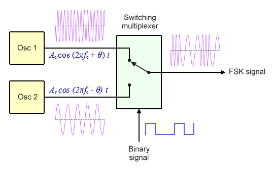
The multiplexer selects the output frequency based on the state of the binary input
The binary signal acts as a select signal, switching the multiplexer output between the mark and space frequencies. If a binary one is received, the multiplexer outputs the mark frequency. If binary zero is received, it outputs the space frequency.
We can achieve the same output using two OOK ASK modulators and an inverter instead of a switching multiplexer, as shown in the block diagram below. The inverter outputs an inverted binary signal, turning all of the binary ones into binary zeros, and vice versa.
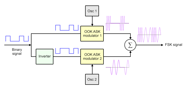
An FSK modulator can be implemented using two OOK ASK modulators
Once again, the mark and space frequencies are generated by two separate local oscillators. The inputs to the first ASK modulator are the mark frequency and the binary signal. It will output a signal at the mark frequency as long as the binary input signal is set to logic high (binary one). The inputs to the second ASK modulator are the space frequency and the inverted binary signal. It will output a signal at the space frequency as long as the inverted signal is set to logic high. In this case, however, a logic high represents binary zero, because the binary signal has been inverted.
Using two separate oscillators means that the mark and space frequencies will be out of phase at the beginning of each bit time. When the modulator switches from one to the other, there will be an abrupt change in both the phase and amplitude of the transmitted signal, and the output is said to be non-coherent. Any abrupt change in the amplitude of the transmitted signal will increase the sideband power, and hence its potential to interfere with signals on adjacent channels. Sharp changes in phase can also increase both signal bandwidth and the probability of bit errors occurring.
As an alternative to using two separate oscillators, the frequency of a single voltage controlled oscillator (VCO) can be switched between two values in order to generate the FSK signal. This has the advantage of guaranteeing that there will be no discontinuity in phase or amplitude when the FSK signal transitions between the mark and space values. The resulting FSK signal is said to be coherent. Coherent FSK modulators tend to cost more than their non-coherent counterparts, so the choice of which type of FSK modulator to use very much depends on the demands of a particular application.
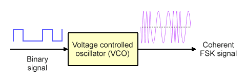
A voltage controlled oscillator (VCO) produces a coherent FSK output
One advantage of eliminating phase discontinuities is that there are no sudden changes in amplitude, which reduces sideband power and makes interference with adjacent channels less likely. A technique known as Gaussian frequency shift keying (GFSK) can be used to further reduce sideband power. GFSK essentially smooths out the edges of the data pulses used to modulate the carrier - a process known as pulse shaping - in order to make the transition between the mark and space frequencies smoother (the trade-off is that it also increases the probability of inter-symbol interference).
Coherent FSK is capable of providing superior performance in terms of both the bit error rate achievable and spectral efficiency. One particularly efficient form of FSK which relies on coherent modulation is called minimum frequency shift keying (MFSK) or sometimes just minimum shift keying (MSK). In this scheme, the difference between the mark and space frequencies is reduced to just half the bit rate, giving it a modulation index of 0.5 (non-coherent FSK requires a modulation index of ≥1.0).
The down side of coherent FSK is that it requires fairly sophisticated circuitry at both the transmitter and the receiver, which increases the overall cost of the transmission system. Non-coherent FSK is considerably simpler to generate, and is used for the majority of FSK transmissions.
FSK demodulators can be categorised as non-coherent (asynchronous) or coherent (synchronous). We'll look first at how a non-coherent demodulator works. The basic components are two bandpass filters, two envelope detectors, and a decision circuit, as shown in the block diagram below.
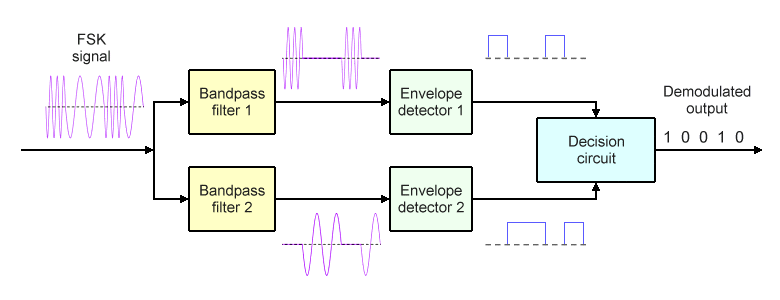
A non-coherent FSK demodulator
Bandpass filter 1 is tuned to the mark frequency and will only allow that frequency to pass. Similarly, bandpass filter 2 is tuned to the space frequency and will only allow that frequency to pass. The output from each of these filters thus resembles an OOK ASK signal, but only one of the bandpass filters will be producing a signal during a given bit time. Each envelope detector circuit consists of a half-wave rectifier and a low-pass filter. Envelope detector 1 rectifies the signal it receives and removes the high frequency components in order to recover the binary ones, while envelope detector 2 performs the same function in order to recover the binary zeros.
During each bit time, the decision circuit compares the signals it receives on each of its inputs, and outputs a binary one or a binary zero, depending on which of the two envelope detectors is generating the strongest signal. In this way, the decision circuit is able to recreate the original binary information signal used by the transmitter to generate the frequency modulated RF signal.
A coherent (synchronous) binary FSK demodulator is so-called because the mark and space frequencies are regenerated at the receiver. As you can see from the block diagram below, the incoming FSK signal is sent to two multipliers. One multiplier receives the locally generated mark frequency as its second input, while the other multiplier receives the locally generated space frequency. The output of each multiplier is then sent to a low pass filter.
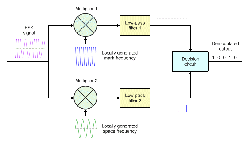
A coherent FSK demodulator
In terms of understanding how coherent FSK detection works, we need to understand what happens in each multiplier, and that requires a certain amount of mathematical analysis. Consider first of all that the incoming FSK signal will, at any given instant, consist of a sinusoidal waveform at either the mark frequency or the space frequency:
VFSK (t) = A cos (2πfc1 ) t = A cos (ωc + Ω) t
or
VFSK (t) = A cos (2πfc2 ) t = A cos (ωc - Ω) t
where A is the FSK signal amplitude, fc1 is the mark frequency, fc2 is the space frequency, ω is the angular frequency of the unmodulated carrier, and Ω is the angular frequency deviation.
Let's consider what happens at each multiplier when a binary one is transmitted, bearing in mind that the incoming signal will be at the mark frequency fc1 . At multiplier 1, the incoming signal will be multiplied together with the locally generated mark frequency:
Mixer 1 output = A cos (ωc + Ω) t · A cos (ωc + Ω) t
Mixer 1 output = A 2 cos 2 (ωc + Ω) t
| Mixer 1 output = A 2 | [ | cos 2 (ωc + Ω) t + 1 | ] |
| 2 |
| Mixer 1 output = | A 2 | + | A 2 | cos 2 (ωc + Ω) t |
| 2 | 2 |
Low-pass filter 1 will remove the high-frequency term, so its output will simply be:
| LPF 1 output = | A 2 |
| 2 |
At multiplier 2, the incoming signal will be multiplied together with the locally generated space frequency:
Mixer 2 output = A cos (ωc + Ω) t · A cos (ωc - Ω) t
Mixer 2 output = A 2 cos (ωc + Ω) t · cos (ωc - Ω) t
| Mixer 2 output = A 2 | [ | cos 2ωc t + cos 2Ω t | ] |
| 2 |
Low-pass filter 2 also removes any high-frequency terms, so its output will simply be zero. The outputs from both low-pass filters are sent to the decision circuit, which compares the inputs from the two low-pass filters and outputs a binary one.
Now let's consider what happens at each multiplier when a binary zero is transmitted. In this case, the incoming signal will be at the space frequency fc2 . At multiplier 1, the signal is multiplied together with the mark frequency:
Mixer 1 output = A cos (ωc - Ω) t · A cos (ωc + Ω) t
Mixer 1 output = A 2 cos (ωc - Ω) t · cos (ωc + Ω) t
| Mixer 1 output = A 2 | [ | cos 2ωc t + cos 2Ω t | ] |
| 2 |
As previously, low-pass filter 1 removes any high-frequency terms, so its output will be zero.
At multiplier 2, the incoming signal is multiplied together with the space frequency:
Mixer 2 output = A cos (ωc - Ω) t · A cos (ωc - Ω) t
Mixer 2 output = A 2 cos 2 (ωc - Ω) t
| Mixer 2 output = A 2 | [ | cos 2 (ωc - Ω) t + 1 | ] |
| 2 |
| Mixer 2 output = | A 2 | + | A 2 | cos 2 (ωc - Ω) t |
| 2 | 2 |
Low-pass filter 2 will remove the high-frequency term, so its output will be:
| LPF 2 output = | A 2 |
| 2 |
Once again, the outputs from both low-pass filters are sent to the decision circuit, which compares the inputs from the two low-pass filters. This time, the output is a binary zero.
The coherent detection of FSK relies on the locally generated mark and space frequencies being in phase with the mark and space frequencies generated by the transmitter. In practical terms, this requires the receiver to recover the frequency and phase information from the incoming signal, which is generally only feasible if the transmitted FSK signal is itself coherent.
Today, FSK demodulator circuits are frequently implemented using phase-locked loops (PLLs) because they are easily incorporated into integrated circuits and provide a highly linear output, and because a variety of cost-effective PLL integrated circuits suitable for this type of application are now widely available. A PLL FSK demodulator essentially works in the same way as the PLL FM demodulator we described in the article "Angle Modulation" in this section, so we will not describe its operation in detail again here.