| Author: | |
| Website: | |
| Page title: | |
| URL: | |
| Published: | |
| Last revised: | |
| Accessed: |
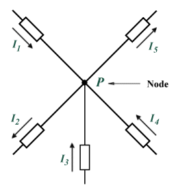
Kirchhoff's current law states that at any node (junction) in a circuit, the current flowing into the node must be equal to the current flowing out of it. Consider the five separate current flows entering or leaving node P in the diagram below. We will adopt the convention of assuming that all currents entering the node are positive, while all currents leaving the node are negative. Thus in the example shown, currents I 1, I 3, and I 4 are positive, while currents I 2 and I 5 are negative. Kirchhoff's current law also states that the sum of all the currents flowing into or out of the node must be zero, so:
I 1 + I 2 + I 3 + I 4 + I 5 = 0

The sum of the currents flowing into and out of the node must be zero
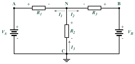
By solving node equations, we can calculate unknown circuit node voltages. In order to make reference to specific nodes in circuit diagrams, we can label them with a letter or number. In the diagram below, the labels A, B, C and N are used to represent nodes. Nodes N and C are what are known as principal nodes. A principal node is one that has three or more connections. We will use node C as a reference node (node voltages for all other nodes will be determined with reference to the potential difference between the node of interest and node C. VAC is the voltage between Nodes A and C; VBC is the voltage between Nodes B and C; and VNC is the voltage between Nodes N and C. Since we have already determined that all node voltages will be determined with reference to node C, we can substitute VA for VAC, VB for VBC, and VN for VNC.

Nodes C and N are principal nodes
In the circuit diagram shown above, we have assumed that currents I 1 and I 2 are leaving node N (i.e. the current is flowing away from node N towards resistors R1 and R3 respectively) and that current I 3 enters (flows into) node N from node C. Such assumptions can often be made intuitively, although the actual direction of current flow may turn out to be in the opposite direction of that assumed. This does not represent a problem, since it simply means that the values obtained by calculation will turn out to have the opposite polarity to that assumed (i.e. negative rather than positive). Kirchhoff's current law states that the currents entering and leaving a node must sum to zero, so based on this and our assumptions about the direction of the current flows we can state the following:
I 1 + I 2 + I 3 = 0
I 1 + I 2 = I 3
Using Ohm's law we can express current flow in terms of voltage and resistance ( I = V/R ) to obtain the following expressions for the currents I 1, I 2 and I 3:
| I 1 = | VA - VN |
| R1 |
| I 2 = | VB - VN |
| R3 |
| I 3 = | VN |
| R2 |
Substituting the expressions thus derived for I 1, I 2 and I 3 into Kirchhoff's current equation gives the following:
| VA - VN | + | VB - VN | = | VN |
| R1 | R3 | R2 |
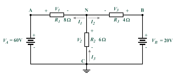
We can use node-voltage analysis to find the unknown voltages and currents in the circuit shown below. The supply voltages and resistance values are known, but we must assume the direction of current flow for currents I 1, I 2 and I 3 and label the nodes (note that I have used the same labelling scheme as in the previous example, and made the same assumptions about the direction of current flow).

We can apply node-voltage analysis to this circuit
Solving for VN:
I 3 = I 1 + I 2 (Kirchoff's current law)
| VN | = | VA - VN | + | VB - VN |
| R2 | R1 | R3 |
| VN | = | 60 - VN | + | 20 - VN |
| 6 | 8 | 4 |
The fractional elements of the equation can be removed by multiplying the equation by the lowest common multiple of the denominators (24):
4VN = 180 - 3VN + 120 - 6VN
13VN = 300
| VN = | 300 | = 23.077 V |
| 13 |
We can now find the remaining voltage drops:
V1 = VA - VN = 60 - 23.077 = 36.923 V
V2 = VN = 23.077 V
V3 = VB - VN = 20 - 23.077 = -3.077 V
Note that the negative value obtained for V3 indicates that the assumption we made about the direction of current flow I 2 through resistor R3 was in fact incorrect. This will be reflected when we calculate the current values for I 1, I 2 and I 3:
| I 1 = | V1 | = | 36.923 V | = 4.615 A |
| R1 | 8 Ω |
| I 2 = | V3 | = | -3.077 V | = -0.769 A |
| R3 | 4 Ω |
| I 3 = | V2 | = | 23.077 V | = 3.846 A |
| R2 | 6 Ω |