| Author: | |
| Website: | |
| Page title: | |
| URL: | |
| Published: | |
| Last revised: | |
| Accessed: |
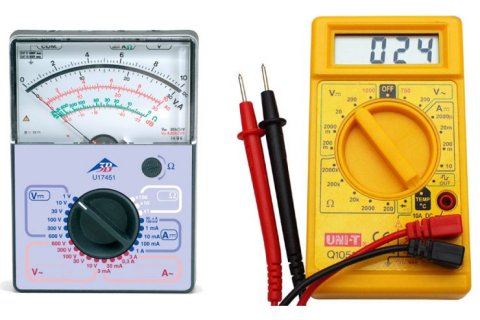
The most commonly used piece of equipment for electrical measurements is the multimeter, which is capable of measuring current (amps), voltage (volts) and resistance (ohms). There are two basic type of multimeter - analogue and digital. Each has advantages and disadvantages, depending upon the type of measurement being taken. Examples of both are shown below:

An analogue multimeter (left) and a digital multimeter (right)
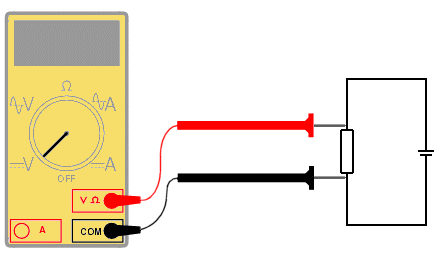
The voltage across a component is a measure of the difference in electrical potential from one side of the component to the other and so the meter must be attached as shown:

Using a multimeter to measure the voltage across a circuit component
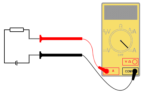
Current is a measure of the rate of flow of electrons through the circuit. To measure the flow of current, the circuit must be broken and the meter must be placed in the circuit such that the current flow goes through it. This is shown below:

Using a multimeter to measure the current through a circuit
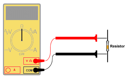
In order to measure resistance, the component must first be removed from the circuit. This is to ensure that the other components in the circuit do not affect the reading. The meter probes are then connected either side of the component as shown:

Using a multimeter to measure the resistance of a circuit component
The table below shows the prefix notation for multiples and submultiples of common electrical units.
| G | giga | 109 | (× 1,000,000,000) |
| M | mega | 106 | (× 1,000,000) |
| k | kilo | 103 | (× 1,000) |
| m | milli | 10-3 | (× 0.001) |
| µ | micro | 10-6 | (× 0.000001) |
| n | nano | 10-9 | (× 0.000000001) |
| p | pico | 10-12 | (× 0.000000000001) |