| Author: | |
| Website: | |
| Page title: | |
| URL: | |
| Published: | |
| Last revised: | |
| Accessed: |
A capacitor is an electronic device that stores charge. It also has the property of preventing the flow of direct current in a circuit while allowing (in practical terms) the flow of alternating current. The simplest form of capacitor consists of two parallel conducting plates, separated by a non-conducting (dielectric) material. The orientation of the capacitor in a circuit depends on the type of dielectric used. A polarised capacitor must be connected so that conventional current enters the capacitor via its positive terminal. For a non-polarised capacitor, current may enter the capacitor through either terminal. The construction of a basic capacitor is illustrated below, together with the circuit diagram symbols used for various types of capacitor.
Construction of a simple capacitor
Capacitor circuit diagram symbols
The ability of a capacitor to store charge is referred to as its capacitance C, which is measured in farads. The farad is the capacitance at which one coulomb is stored for a potential difference of one volt. Most of the capacitors used in electronic circuits have a capacitance value that is only a very small (sometimes miniscule) fraction of a farad, so the following units are often used when talking about the value of a capacitor:
10-6 farads = 1 microfarad (μF)
10-9 farads = 1 nanofarad (nF)
10-12 farads = 1 picofarad (pF)
Typical capacitances vary from 1 picofarad up to about 0.15 farads. The capacitance of a particular capacitor depends on the area of the conducting plates (the larger the area, the greater the capacitance), the distance between the plates (to which the capacitance is inversely proportional) and the relative permittivity of the dielectric material between the plates, the significance of which is discussed in more detail below. The capacitor selected for a specific application will depend on the capacitance required, the acceptable tolerance, and the degree of stability needed. Two additional factors are also important:
The permittivity ε of a medium is the ratio D/E where D is the electric displacement (or flux density ) in coulombs per square metre (C/m2) and E is the electric field strength (or potential gradient ) in volts per metre (V/m). Permittivity is specified in farads per metre (F/m). It can also be defined as a dimensionless relative permittivity (εr) relative to the permittivity of free space (ε0) which is equal to 8.854187817 x 10⁻¹² F/m. The absolute permittivity of the dielectric material can therefore also be expressed as:
ε = ε0εr
From the above, it can be seen that the electric field strength E will become smaller as the value of ε increases. This is because dielectric materials with a higher permittivity are more easily polarised when brought into contact with a charged conductor. The polarisation creates an internal electric field within the dielectric material that opposes the external field created by the charge, and thereby reduces its overall field strength. As charge accumulates, the electric field it creates grows stronger and increasingly opposes the further buildup of charge, limiting the total amount of charge that may accumulate on the conductor. Any reduction in field strength will therefore allow a larger amount of charge to accumulate for a given applied voltage, and by definition increase capacitance. The charge density σ on the conducting plates of a capacitor d metres apart is given by:
| σ = ε × | V |
| d |
and the capacitance C per unit area is given by:
| C = | ε |
| d |
Capacitors can be tested using a multimeter. For non-polarised types, the resistance through the capacitor can be tested regardless of which of the multimeter terminals is attached to the positive or negative terminals of the capacitor. If the resistance is found to be less than about 1 MΩ, the capacitor is allowing d.c. current from the multimeter to pass through it and is probably faulty, since current is leaking through it (note that for large value capacitors, there may be a short initial burst of current as the capacitor charges). When testing electrolytic (polarised) capacitors, remember that a positive voltage must be applied to the positive terminal of the capacitor order for the dielectric to form, so check the polarity of the multimeter's terminals before connecting them to the capacitor. When the capacitor is connected to the multimeter its resistance will initially be low, but will increase as the dielectric forms. If this does not happen, the capacitor is probably faulty.
Fixed capacitors can be classified according to the dielectric material used, since their properties depend on it. The polyester, mica and ceramic types described below are non-polarised, while the electrolytic types are polarised. In polyester capacitors, two strips of polyester film (the dielectric) are wound between two strips of aluminium foil (the conducting plates). Each strip of foil is connected to one of the capacitor's leads. In a variation on this type of capacitor, a metal film is deposited on the surface of the polyester strips to form the conducting plates. This type of capacitor's small size, low cost and reliability make it suitable for a wide range of applications. Capacitance values range from 500 pF to 10 μF, and the capacitance (in picofarads) used to be marked using the same colour coding scheme as that used for resistors. Polycarbonate capacitors are similar to polyester capacitors in construction but are more stable and have a lower leakage current, although they are also more expensive.
Polyester capacitor construction and a typical polyester capacitor
Mica capacitors are constructed using mica, a naturally occurring mineral that can be split into very thin sheets of uniform thickness. The plates of the capacitor are formed by depositing a silver film onto the mica, or by using interleaved sheets of aluminium foil. Mica capacitors are characterised by low tolerances (± 1%), high working voltages, and a low leakage current. They are also very stable, but can only be manufactured with relatively low capacitance values (up to 0.01 μF). They are used in radio frequency tuned circuits where low loss is important. Polystyrene capacitors have similar properties and are cheaper than mica capacitors, although their performance cannot match that of mica capacitors. For a multi-plate capacitor such as the one illustrated below, the capacitance is that of one pair of plates multiplied by the total number of pairs (or by the total number of plates minus one).
Mica capacitor construction and a typical mica capacitor
Various types of ceramic capacitors are available, depending on the type of ceramic material used. One type has similar properties to the mica capacitor and is used in radio frequency circuits. Another type gives high capacitance values with a relatively small package, but stability and tolerance are poor. This second type can be used where exact values are not particularly important. Ceramic capacitors come in a range of formats, and may be in the shape of a disc, rod or plate. A disc shaped ceramic capacitor is shown below.
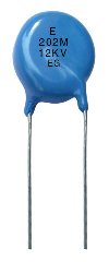
A disc-shaped ceramic capacitor
In an aluminium electrolytic capacitor, the dielectric is a very thin layer of aluminium oxide that is formed by a process of electrolysis. Electrolytic capacitors can provide high capacitance values (up to 150,000 μF) in a relatively small package and at a low cost. On the down side, tolerances can vary between -20% and +100% of the rated value, and they exhibit a high leakage current and poor stability. They tend to be used in applications where high capacitance values are required and exact capacitance values are unimportant, such as power supply equipment. Because electrolytic capacitors are polarised, their positive terminal is usually marked with a groove or a plus sign (+). Often, the aluminium casing itself is the negative terminal. The d.c. leakage current maintains the oxide layer, so an inadvertently reversed polarity (or lack of use) can cause the dielectric to deteriorate. Another type of electrolytic capacitor, the tantalum capacitor, can be used as an alternative to aluminium types in low-voltage circuits requiring capacitances of no more than 100 μF. Tantalum capacitors have lower leakage currents.
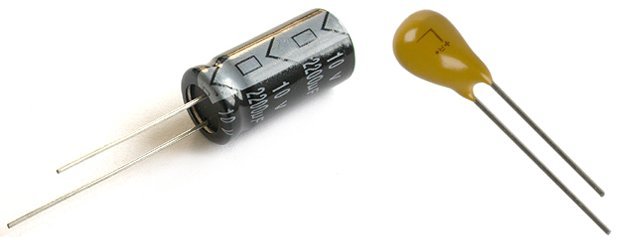
Aluminium (left) and tantalum (right) electrolytic capacitors
Variable capacitors are mainly used to tune radio receivers, and consist of two sets of parallel metal plates. One set is fixed and the other moves on a spindle, interleaving itself with the fixed set. The plates are separated by a dielectric (usually air). Sometimes, two or more variable capacitors are ganged together on the same spindle so that the capacitance in several circuits can be changed simultaneously when the spindle is rotated. The maximum capacitance that can be achieved with the plates fully interleaved is in the order of 500 pF for a single unit. Another type of variable capacitor is the trimmer capacitor, a small variable capacitor used to make fine adjustments to the capacitance of a circuit. The second capacitor illustrated below shows the mica compression type, in which metal foil and mica sheets are compressed to a greater or lesser degree by turning a screw. This changes the capacitance by a very small amount.
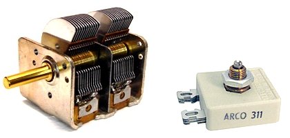
An air variable capacitor (left) and a mica compression capacitor (right)
A capacitor can be charged by connecting a battery across it, as shown in the diagram below. When the switch is closed, electrons from the upper plate (X) of the capacitor are attracted to the positive terminal of the battery. An equal number of electrons are repelled by the negative terminal and move to the lower plate (Y). A positive charge builds up on X, while a negative charge builds up on Y. While the charging process continues, electrons move along the connecting wires but are prevented from crossing the gap between the plates by the non-conducting dielectric material (for the purposes of this discussion we will assume this is a perfect capacitor and ignore leakage current). A brief current would be detected in the circuit by a sensitive meter during charging.
A capacitor in a d.c. circuit
After a short period of time (the duration of which would depend on the capacitance of the capacitor, the internal resistance of the battery, and the resistance of the connecting wires) the potential difference (voltage) between X and Y will be equal and opposite to the terminal voltage of the battery. The flow of electrons stops, and current falls to zero. The charge on plate X will be +Q, and the charge on plate Y will be -Q (note that the net charge on the capacitor is always equal to zero). The charge said to be stored by the capacitor is simply referred to as Q. Once the capacitor has become fully charged, the following expression is true:
| V = | Q |
| C |
Where:
V = the potential difference between the plates in volts
Q = the total charge stored in coulombs
C = the capacitance of the capacitor
Increasing the voltage will increase the amount of charge stored by the capacitor in direct proportion to the increase in voltage. We can rearrange the above formula to find the charge Q for a capacitor of known capacitance C when an applied voltage of V is connected across it as follows:
Q = VC
The energy stored by a capacitor comes from whatever charged it (in the circuit we have just looked at, this is a battery). Consider the circuit diagram below. Assume that switch B is initially open, and that the capacitor has been fully charged. Switch A has now been opened which means that the capacitor is no longer part of a circuit and the charge stored in the capacitor cannot discharge itself. If switch B is now closed, a current will flow through the circuit, lighting the lamp. The lamp will only be lit very briefly since the amount of energy stored by a capacitor is tiny compared to that stored by a battery, and the capacitor will quickly lose its charge. Some of the electrical energy supplied by the battery and stored by the capacitor, however, has been changed into a different form of energy (in this case light, as well as heat dissipated by the lamp).
Energy stored in a capacitor can be used to light a lamp
The energy (measured in joules) stored by a capacitor is equal to the work done to charge it. It can be shown that the energy W stored by a capacitor is given by the expression:
W = ½ QV
Since Q = VC we also have:
W = ½ V 2C
And since V = Q/C:
| W = ½ | Q2 |
| C |
Standard capacitors are sometimes connected together in parallel to give a larger capacitance, in the same way that resistors are sometimes connected in series to give a greater resistance. To find the total capacitance of two or more capacitors in parallel, simply add the capacitances together. In the diagram below, two capacitors with capacitances C1 and C2 are connected in parallel with a battery producing a terminal voltage V.
Capacitors in parallel
The voltage V will be the same across each capacitor, but the charges stored on each (Q1 and Q2) will be determined by their respective capacitances and are given by:
Q1 = V × C1
Q2 = V × C2
The total charge QTOTAL on both capacitors is given by:
QTOTAL = Q1 + Q2 = V(C1 + C2)
The behaviour of capacitors in series is similar to the behaviour of resistors in parallel in that the total capacitance of two or more capacitors in series will be less than that of the lowest valued capacitor, just as two or more resistors in parallel have a lower total resistance than the lowest valued resistor. To find the total capacitance of two or more capacitors in series, you add the reciprocals of the capacitances together, and then take the reciprocal of the result. In the diagram below, two capacitors with capacitances C1 and C2 are connected in series with a battery.
Capacitors in series
The formula for finding the combined capacitance CTOTAL of two or more capacitances in series is similar to that used to find the combined resistance of resistors in parallel:
| 1 | = | 1 | + | 1 | + | 1 | + · · · |
| CTOTAL | C1 | C2 | C3 |
And:
| CTOTAL = | 1 | ||||||||
|
The total capacitance of two capacitors in series is equal to the product of the two capacitances divided by their sum (Note, however, that this formula can only be applied to two capacitors in series. For three or more capacitors in series, the formula shown above must be used):
| CTOTAL = | C1 × C2 |
| C1 + C2 |