| Author: | |
| Website: | |
| Page title: | |
| URL: | |
| Published: | |
| Last revised: | |
| Accessed: |
Fibre Distributed Data Interface (FDDI) was developed by ANSI in the mid-1980s and specifies a 100-Mbps token-passing dual-ring LAN using fibre-optic cable, which is frequently used as high-speed backbone technology because of its high bandwidth and the distances it can span (up to 100 kilometres). Due to the advent of fast Ethernet and Gigabit Ethernet, the complexity of station management in FDDI networks, and its high cost, FDDI has never gained a foothold in the LAN market. The dual-ring system consists of a primary and a secondary ring, in which traffic on each ring flows in opposite directions. In normal operation, the primary ring is used for data transmission and the secondary ring remains idle. Up to 1000 devices can be connected to an FDDI network, with up to two kilometres between stations is using multi-mode fibre, and even longer distances using single-mode fibre. There are various ways in which FDDI devices can be connected to the network. A single attachment station (SAS) is attached to the primary ring, usually via a concentrator. Concentrators are devices which are similar in many ways to hubs on an Ethernet network, and are usually dual attachment concentrators, attached to both rings. A dual attachment station (DAS) is attached directly to both the primary and secondary rings.
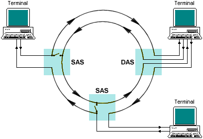
FDDI dual-ring architecture
The main reason for the second ring is to provide fault tolerance in the event of a primary ring failure. Traffic can wrap around a problem node and continue to carry data on the secondary ring (in the opposite direction). If two nodes fail, the wrap at two locations effectively creates two separate (non-communicating) rings. Bypass devices called concentrators can be used to overcome such problems. These devices resemble hubs or MSAUs in that multiple nodes can be connected to them. They can also isolate failed nodes, while maintaining network traffic. In certain circumstances, both rings are used to carry data, effectively doubling the capacity of the network. The following diagram illustrates the effect of a ring wrapping in FDDI.
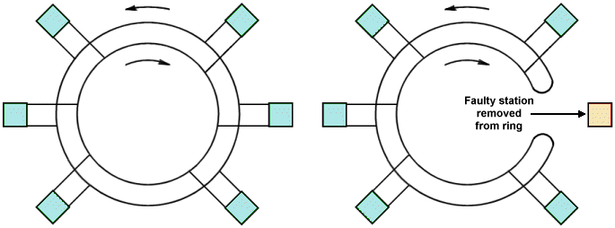
Ring-wrapping in an FDDI network
An alternative to wrapping is to use an optical bypass switch. This device provides continuous dual-ring operation if a device on the ring fails. It prevents ring segmentation and eliminates the failed station from the ring. Each DAS has two ports, designated A and B. These ports connect the DAS to both the primary and secondary rings. Devices using DAS connections will affect the ring if they are disconnected or powered off. If the DAS device fails, the switch passes the light through itself using internal mirrors, maintaining the integrity of the ring.
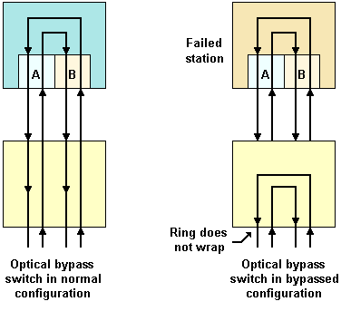
An optical bypass switch in an FDDI network
FDDI frames are similar to Token Ring frames, and can be up to 4,500 bytes in length. The FDDI frame fields are summarised below.

The FDDI frame format