| Author: | |
| Website: | |
| Page title: | |
| URL: | |
| Published: | |
| Last revised: | |
| Accessed: |
Various physical media can be used to transport a stream of bits from one device to another. Each has its own characteristics in terms of bandwidth, propagation delay, cost, and ease of installation and maintenance. Media can be generally classified as guided (e.g. copper and fibre cable) and unguided (wireless) media. The main categories of transmission media used in data communications networks are listed below (please note that wireless transmission media will be dealt with elsewhere).
Twisted pair copper cable is still widely used, due to its low cost and ease of installation. A twisted pair consists of two insulated copper cables, twisted together to reduce electrical interference between adjacent pairs of wires. This type of cable is still used in the subscriber loop of the public telephone system (the connection between a customer and the local telephone exchange), which can extend for several kilometres without amplification. The subscriber loop is essentially an analogue transmission line, although twisted pair cables are also be used in computer networks to carry digital signals over short distances.
The bandwidth of twisted pair cable depends on the diameter of wire used, and the length of the transmission line. The type of cable currently used in local area networks has four pairs of wires. Until recently, category 5 or category 5E cable has been used, but category 6 is now used for most new installations. The main difference between the various categories is in the data rate supported - category 6 cable will support gigabit Ethernet. The main disadvantage of UTP cables in networks is that, due to the relatively high degree of attenuation and a susceptibility to electromagnetic interference, high speed digital signals can only be reliably transmitted over cable runs of 100 metres or less.
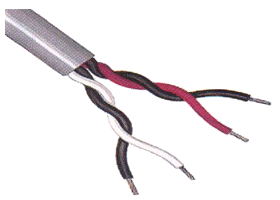
Unshielded twisted pair cable
Shielded Twisted Pair (STP) cable was introduced in the 1980s by IBM as the recommended cable for their Token Ring network technology. It is similar to unshielded twisted pair cable except that each pair is individually foil shielded, and the cable has a braided drain wire that is earthed at one end during installation. The popularity of STP has declined for the following reasons:
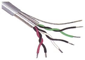
Shielded twisted pair cable
A coaxial cable has a central copper wire core, surrounded by an insulating
(dielectric) material. Braided metal shielding surrounds the dielectric and
helps to absorb unwanted external signals (noise), preventing it from
interfering with the data signal travelling along the core. A plastic sheath
protects the cable from damage. A terminating resistor is used at each end of
the cable to prevent transmitted signals from being reflected back down the
cable. The following diagram illustrates the basic construction of a coaxial
cable.
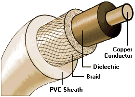
Construction of coaxial cable
Coaxial cable has a fairly high degree of immunity to noise, and can be used
over longer distances (up to 500 metres) than twisted pair cable. Coaxial cable
has, in the past, been used to provide network backbone cable segments. Coaxial
cable has largely been replaced in computer networks by optical fibre and
twisted pair cable, with fibre used in the network backbone, and twisted pair
used to connect workstations to network hubs and switches.
Thicknet cable (also known as 10Base5) is a fairly thick cable (0.5 inches in
diameter). The 10Base5 designation refers to the
10 Mbps maximum data rate
,
baseband signalling
and
500 metre maximum segment length
. Thicknet was the original transmission medium used in Ethernet networks, and
supported up to 100 nodes per network segment. An ethernet tranceiver was
connected to the cable using a
vampire tap
, so called because it clamps onto the cable, forcing a spike through the outer
shielding to make contact with the inner conductor, while two smaller sets of
teeth bite into the outer conductor. Transceivers could be connected to the
network cable while the network was live. A separate
drop
cable with an
attachment unit interface
(AUI) connector at each end connected the tranceiver to the network interface
card in the workstation (or other network device). The drop cable was typically
a shielded twisted pair cable, and could be up to 50 metres in length. The
minimum cable length between connections (
taps
) on a cable segment was 2.5 meters.
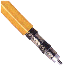
Thicknet (10Base5) coaxial cable
Thinnet cable (also known as 10Base2) is thinner than Thicknet (approximately
0.25 inches in diameter) and as a consequence is cheaper and far more flexible.
The 10Base2 designation refers to the
10 Mbps maximum data rate
,
baseband signalling
and
185 (nearly 200) metre maximum segment length
. A T-connector is used with two BNC connectors to connect the network segment
directly to the network adapter card. The length of cable between stations must
be at least 50 centimetres, and Thinnet can support up to 30 nodes per network
segment.
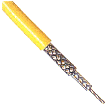
Thinnet (10Base2) coaxial cable
Optical fibres are thin, solid strands of glass that transmit information as
pulses of light. The fibre has a core of high-purity glass, between 6μm and
50μm in diameter, down which the light pulses travel. The core is encased
in a
covering layer made of a different type of glass, usually about 125 μm in
diameter, known as the cladding. An outer plastic covering, the primary buffer,
provides some protection, and takes the overall diameter to about 250 μm.
The
structure of an optical fibre is shown below.
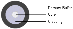
The basic construction of an optical fibre
The cladding has a slightly lower refractive index than the core (typical values are 1.47 and 1.5 respectively), so that as the pulses of light travel along the fibre they are reflected back into the core each time they meet the boundary between the core and the cladding. Optical fibres lose far less of its signal energy than copper cables, and can be used to transmit signals of a much higher frequency. More information can be carried over longer distances with fewer repeaters. The bandwidth achievable using optical fibre is almost unlimited, but current signalling technology limits the data rate to 1 Gbps due to time required to convert electronic digital signals to light pulses and vice versa. Digital data is converted to light pulses by either a light emitting diode (LED) or a laser diode. Although some light is lost at each end of the fibre, most is passed along the fibre to the receiver, where the light pulses are converted back into electronic signals by a photo-detector.
As the ray passes along the fibre it meets the boundary between the core and the cladding at some point. Because the refractive index of the cladding is lower than that of the core, the ray is reflected back into the core material, as long as the angle of incidence ( θ i ) is greater than the critical angle ( θ c ). The critical angle depends on the refractive indices of the two materials. In the case of an optical fibre, the values are chosen so that almost all of the light is reflected back into the fibre, and there is virtually no loss through the walls of the fibre. This is called total internal reflection . The critical angle for a particular fibre can be calculated using Snell's Law. This states that:
n 1 sin θ 1 = n 2 sin θ 2
where θ
1
is the angle of incidence, θ
2
is the angle of refraction, and n
1
and n
2
are the refractive indices of the core and cladding respectively. The effect
on a ray of light passing along the fibre is shown below.
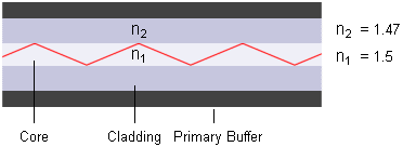
Light transmission in an optical fibre
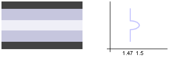
In
step-index
fibres, the refractive index of both the core and the cladding has a constant
value, so that the refractive index of the fibre steps from one value to the
next.

A step-index fibre
If the core diameter of the fibre is such that it allows light to enter at
different angles and follow multiple paths, it is said to be a
multi-mode
fibre. The number of times the light is internally reflected will vary
according to the angle at which the light initially enters the fibre, which
will in turn determine the path length of the light as it travels along the
fibre. Over long distances, there will be a significant difference in path
length between light rays that enter the fibre at different angles. They will,
as a consequence, arrive at slightly different times, causing distortion of the
transmitted signal - an effect known as
modal dispersion
. For this reason, multi-mode fibres are only used for short-haul applications
such as LAN backbone connections, where the distances involved are likely to
be considerably less than one kilometre.

A multi-mode step-index fibre
If the core diameter of the fibre is made small enough, the angle at which
light can enter the fibre can be limited such that most of the light travels
down a single path, effectively eliminating modal dispersion. This type of
fibre is called a mono-mode fibre, and is commonly used for long-haul
applications such as long distance telecommunications. Distances of many
kilometres are possible with mono-mode fibre before a repeater is needed.

Multi-mode and mono-mode fibres
One way to improve the performance of multi-mode fibre is to use a
graded index fibre
instead of a step index fibre. The refractive index of this type of fibre
varies across the diameter of the core in such a way that light is made to
follow a curved path along the fibre (see below). Light near the edges of the
core travels faster than light at the centre of the core, so although some rays
follow a longer path than others, they all tend to arrive at the same time,
resulting in far less modal dispersion than would occur in a step-index
multi-mode fibre.
A graded index fibre

Light paths in a graded index fibre